Contents
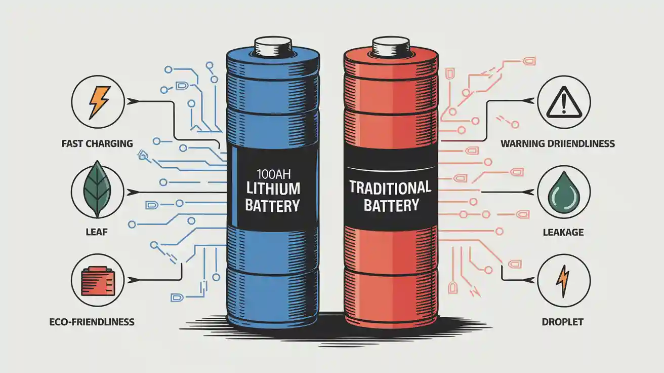
Minimizing electromagnetic interference (EMI) in lithium battery systems is essential for enhancing both performance and safety. EMI can interfere with vital components such as cables and connectors, potentially causing system failures. By implementing strategies like grounding, shielding, optimizing PCB layouts, and using filtering techniques, the reliability of lithium battery systems can be significantly improved. Additionally, incorporating wireless communication helps reduce EMI and boosts the mileage per charge.
Key Takeaways
Use good grounding methods to give unwanted signals a clear path. This lowers interference and makes the system work better.
Add shielding like Faraday cages or shielded wires to stop noise. This keeps parts safe and meets industry rules.
Design PCB layouts with space between power and signal lines. This cuts down interference and helps lithium battery systems work well.
Part 1: Understanding EMI and Lithium Battery Systems
1.1 What is Electromagnetic Interference (EMI)?
Electromagnetic interference refers to the disruption caused by electromagnetic waves that affect the performance of electronic devices. It can occur in two primary forms: conducted EMI and radiated EMI. Conducted EMI arises from direct contact between conductors, while radiated EMI propagates through induction without physical contact. At lower frequencies, interference is mainly conducted, whereas higher frequencies result in radiated interference.
To better understand EMI, consider the following classifications:
Type of Interference | Description |
|---|---|
Permissible Interference | Does not cause harmful effects. |
Accepted Interference | Acknowledged but may still impact device performance. |
Harmful Interference | Causes detrimental effects on device operation. |
Understanding these types helps you identify and address EMI issues effectively in lithium battery systems.
1.2 Why EMI Matters in Lithium Battery Systems
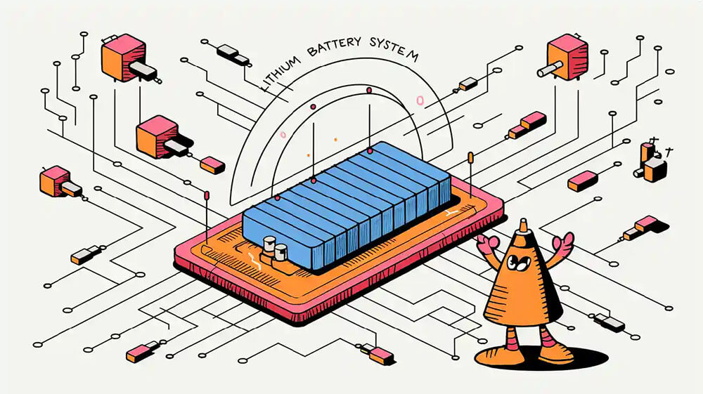
EMI and lithium battery systems are closely linked due to the sensitivity of battery management systems (BMS) and other electronic components. Electromagnetic interference can compromise the operational safety of these systems by disrupting communication between components or causing malfunctions.
Addressing EMI is critical for ensuring electromagnetic compatibility and maintaining system reliability. Suppressing emissions, weakening propagation paths, and enhancing circuit immunity are essential strategies. Techniques like shielding, filtering, and grounding play a vital role in mitigating interference and ensuring safe performance.
1.3 Key EMI Challenges in Battery Applications
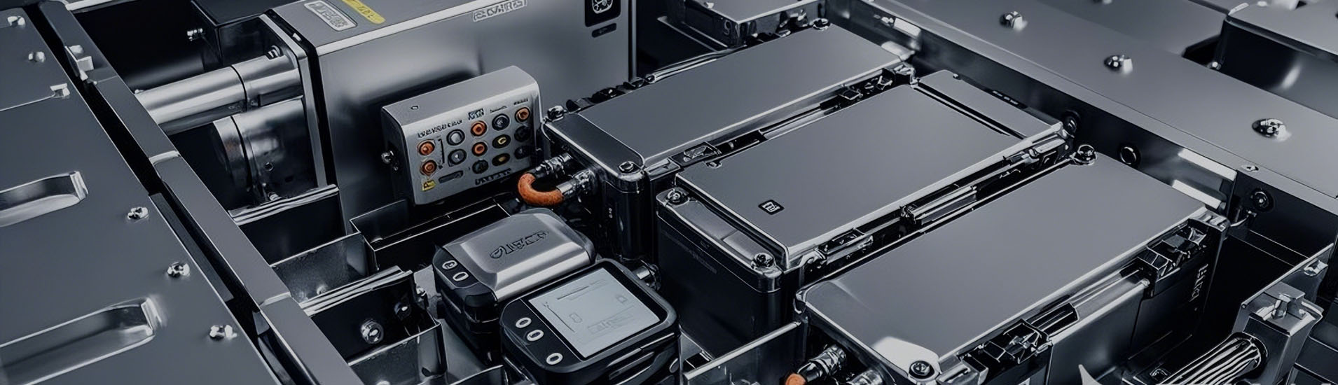
Lithium battery systems face unique challenges related to EMI. High-frequency switching in BMS generates significant interference, while compact designs and dense component placement exacerbate the problem. Environmental factors, such as nearby radio frequency sources, further contribute to EMI issues.
To overcome these challenges, you can implement solutions like onboard EMI filters, shielding materials such as RF gaskets, and optimized PCB layouts. These measures enhance electromagnetic compatibility and reduce interference, ensuring the stability and efficiency of lithium battery systems.
Part 2: Causes of Electromagnetic Interference in Lithium Battery Systems
2.1 High-Frequency Switching in Battery Management Systems (BMS)
High-frequency switching in battery management systems (BMS) is one of the primary sources of electromagnetic interference. The rapid switching of power electronics in the BMS generates voltage and current ripples, which can lead to increased losses and reduced component lifespans. These ripple effects also create challenges related to conducted electromagnetic interference, impacting the system’s electromagnetic compatibility (EMC).
Additionally, high-frequency switching can cause voltage and current transients. These transients may result in damaging overvoltage conditions, compromising the integrity of components and the overall EMC performance. For instance:
Voltage and current ripple can degrade the efficiency of the system and shorten the lifespan of components.
Transients caused by switching can lead to severe overvoltage, especially when contactors in the battery pack open suddenly.
The battery pack itself may generate dangerous transients, further exacerbating interference issues.
To mitigate these effects, you should consider implementing advanced filtering techniques and optimizing switching frequencies. These measures can help suppress noise and improve the system’s immunity to interference.
2.2 Compact Designs and Dense Component Placement
The trend toward compact designs and dense component placement in lithium battery systems has introduced new challenges in managing electromagnetic interference. As devices become smaller, the proximity of components increases, which can lead to unintended coupling of electromagnetic fields. This coupling often results in higher levels of conducted electromagnetic interference and radiated noise.
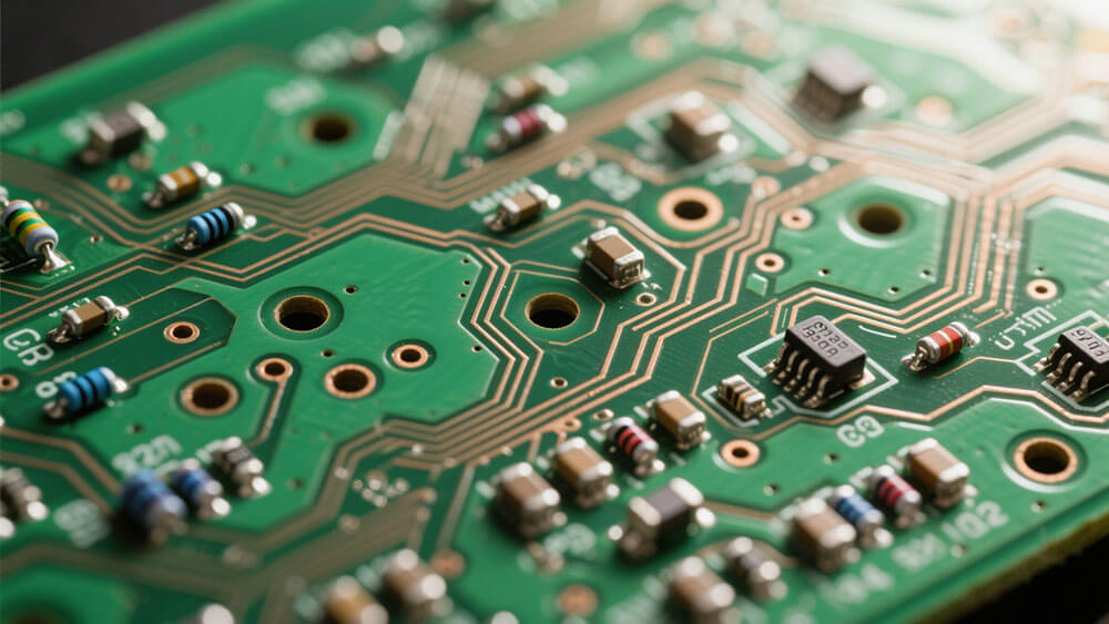
In tightly packed systems, the lack of physical separation between components makes it easier for interference to propagate. For example, power and signal traces on a printed circuit board (PCB) may inadvertently act as antennas, amplifying interference. Furthermore, the reduced space limits the effectiveness of shielding measures, making it harder to isolate sensitive components from noise sources.
To address these challenges, you should focus on optimizing PCB layouts. Techniques such as separating high-power and low-power circuits, minimizing loop areas, and using ground planes can significantly reduce interference. Additionally, incorporating shielding measures like RF gaskets can help contain electromagnetic emissions and protect sensitive components.
2.3 Environmental Factors Contributing to EMI
Environmental factors play a significant role in the generation and propagation of electromagnetic interference in lithium battery systems. External sources, such as nearby radio frequency (RF) transmitters, can introduce radiated interference that disrupts the operation of sensitive components. Similarly, environmental noise from industrial equipment or power lines can exacerbate conducted electromagnetic interference.
Temperature fluctuations and humidity levels also affect the performance of shielding measures and other EMI mitigation techniques. For instance, high temperatures can degrade the materials used in shielding, reducing their effectiveness over time. Humidity can lead to condensation, which may create unintended conductive paths and increase the risk of interference.
To minimize the impact of environmental factors, you should implement robust shielding measures and ensure proper grounding. Using materials that can withstand harsh environmental conditions will enhance the durability and effectiveness of EMI mitigation strategies. Additionally, conducting regular system testing in real-world conditions can help identify and address potential vulnerabilities.
Part 3: Practical Methods to Reduce Electromagnetic Interference
3.1 Grounding Techniques for EMI Reduction
Effective grounding techniques play a pivotal role in suppressing electromagnetic interference in lithium battery systems. Grounding provides a low-resistance path for unwanted signals, ensuring they dissipate safely without affecting system performance. You can implement strategies such as single-point grounding, which minimizes ground loops, or multi-point grounding for high-frequency applications.
To enhance grounding effectiveness:
Use ground planes in PCB designs to reduce impedance and improve signal integrity.
Ensure proper bonding between metallic components to eliminate potential differences.
Avoid sharp bends in grounding paths, as they can act as antennas and amplify interference.
Grounding techniques are particularly critical in electric vehicle power systems, where high-frequency switching and compact designs increase EMI risks. By prioritizing robust grounding practices, you can significantly reduce electromagnetic interference and improve system reliability.
3.2 Shielding to Minimize External and Internal Interference
Electromagnetic shielding is one of the most effective methods to suppress electromagnetic interference. Shielding materials block or absorb electromagnetic noise, preventing it from coupling with sensitive components. You can use techniques like Faraday cages, shielded cables, and conductive enclosures to mitigate both external and internal interference.
Shielding Technique | Description |
|---|---|
Faraday Cage | An enclosure made of conductive material that blocks electromagnetic fields. |
Shielded Cables | Cables with metallic braiding or foil wrapping to prevent electromagnetic noise from coupling. |
Enclosure Shielding | Conductive enclosures that block external EMI using materials like copper, aluminum, and steel. |
Grounding and Bonding | Ensures unwanted signals have a low-resistance path to dissipate, reducing potential differences. |
EMI Filters | Blocks high-frequency noise while allowing power and signals to pass. |
RF Absorbers | Materials that absorb electromagnetic waves and convert them into heat. |
Gasketing and Coatings | Enhances shielding effectiveness by sealing openings in metallic casings. |
PCB Shielding | Techniques like using ground planes and shielding cans to protect sensitive circuits on PCBs. |
Adding fillers like carbon fibers or metal fibers to shielding materials can enhance their effectiveness. For automotive applications, shielding effectiveness levels typically range from 40 dB to 80 dB, depending on the standard. By incorporating these techniques, you can suppress electromagnetic interference and ensure compliance with industry standards.
3.3 Optimizing PCB Layout for EMI and Lithium Battery Systems
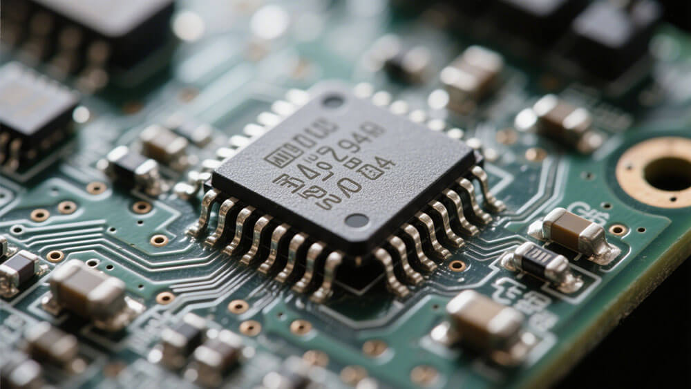
PCB layout optimization is crucial for reducing electromagnetic interference in lithium battery systems. Poor PCB design can lead to unintended coupling of electromagnetic fields, amplifying interference. You can follow these design guidelines to minimize EMI:
Use ground fill gridding to improve grounding and reduce noise propagation.
Place ferrite beads strategically to suppress high-frequency noise.
Maintain proper separation between power and signal traces to prevent coupling.
Route return paths efficiently to minimize loop areas.
These strategies have been validated through statistical outcomes, demonstrating measurable EMI reduction. For example, efficient routing of return paths can significantly reduce radiated emissions, while proper component separation minimizes conducted interference. By optimizing PCB layouts, you can enhance electromagnetic compatibility and improve the performance of lithium battery systems.
3.4 Using Filters and Capacitors to Suppress Noise
Filters and capacitors are essential tools for suppressing electromagnetic interference in lithium battery systems. Ground noise filters reduce conducted line emissions, ensuring the reliability of electronic control equipment. Capacitors, particularly Y-capacitors, play a key role in diminishing radiated EMI across frequency bands.
Testing has shown that filter performance varies with impedance and load, highlighting their adaptability to different electrical conditions. For example:
At 30 MHz, a Y-capacitor with a capacitance exceeding 86 pF ensures insertion loss below 1.
At 167 MHz, a Y-capacitor with a capacitance exceeding 30 pF achieves similar performance.
Frequency (MHz) | Capacitive Requirement (pF) | Inductive Requirement (nH) |
|---|---|---|
30 | > 86 | < 327 |
167 | > 30 | < 30 |
The choice of filtering elements is critical for effective EMI suppression. By evaluating filter technology under real-world conditions, you can ensure their reliability against transient currents and optimize noise reduction.
3.5 Selecting EMI-Compliant Components for Battery Systems
Choosing EMI-compliant components is essential for ensuring system reliability and compliance with industry standards. Components must meet specific emissions and immunity requirements, depending on the region and application.
Region / Marking | Emissions Required | Immunity Required | Self-Declaration Allowed | Notable Notes |
|---|---|---|---|---|
FCC (USA) | Yes | No | Yes, limited to Part 15B radiated and conducted emissions | Focuses on radiated and conducted emissions. Immunity testing is not required. |
CE (EU) | Yes | Yes | Yes | Requires both emissions and immunity testing under the EMC Directive using harmonized EN standards. |
UKCA (UK) | Yes | Yes | Yes | Technical requirements mirror CE. Separate documentation and declaration process. |
ISED (Canada) | Yes | No | Yes (with accredited lab testing) | Requires emissions testing from ISO 17025-accredited labs. Immunity testing is not required. |
VCCI (Japan) | Yes | No | Yes (after registration) | Applies to IT and digital devices. Focused on emissions only. Voluntary, but widely followed. |
Pre-compliance scans, radiated emissions testing, and electrostatic discharge testing are critical for verifying component compliance. By selecting EMI-compliant components, you can suppress electromagnetic interference and ensure the stability of lithium battery systems.
Addressing EMI in lithium battery systems ensures reliability, safety, and compliance with industry standards. Practical methods like grounding, shielding, and PCB optimization reduce interference effectively.
Adopting these techniques strengthens system stability and enhances performance. By prioritizing EMI mitigation, you can design robust battery systems that meet modern demands and regulatory requirements.
FAQ
1. What is the role of EMI shielding in a lithium battery system?
EMI shielding blocks electromagnetic noise, protecting your system’s sensitive components. It ensures reliable operation and compliance with industry standards.
2. How does grounding improve the performance of a battery system?
Grounding provides a low-resistance path for unwanted signals. This reduces interference and enhances the overall stability of your system.
3. Why is PCB layout optimization critical in a lithium battery system?
Optimizing PCB layouts minimizes electromagnetic interference. It ensures efficient signal routing and improves the electromagnetic compatibility of your system.
Tip: For professional guidance on PCB layout optimization, visit Large Power.