
Did you know a Battery Management System (BMS) protects cells from dangerous conditions that can trigger thermal runaway and combustion? This vital technology guards modern battery packs, especially when you have lithium-ion cells. These cells pack the highest energy density but need careful monitoring.lithium-ion
A BMS keeps track of voltage, current, and temperature to keep batteries running safely. These smart systems can handle battery packs from less than 100V up to 800V, and the supply currents are a big deal as it means that 300A. The BMS does more than simple monitoring – it protects against overcharging and deep discharge while making the battery perform better.
Engineers working with lithium battery management systems need to understand cell balancing well. The BMS maintains charge balance between individual cells through active and passive methods. This substantially improves the battery’s lifespan and efficiency. A balanced system prevents degradation and maximizes capacity across the battery pack.
In this piece, we’ll learn about how BMS technology works with vehicle systems like thermal management and charging infrastructure. On top of that, we’ll get into how predictive analytics and machine learning reshape the scene of battery management systems. These advances allow more proactive monitoring of battery health and performance.
Understanding What is a Battery Management System (BMS)

Image Source: ResearchGate
The battery management system (BMS) acts as the electronic brain of modern rechargeable batteries. It monitors and controls vital functions that optimize performance and safety. A BMS offers more than simple protection circuit modules (PCMs). It provides complete management capabilities that help batteries last longer and prevent dangerous failures.
Definition of BMS and Core Functions
A battery management system is an electronic system that takes care of rechargeable batteries. It tracks how they work, calculates their status, reports data, controls their environment, and helps them operate safely throughout their life. Mercedes CEO Dieter Zetsche put it well when he said, “The intelligence of the battery does not lie in the cell but in the complex battery system”.
The core functions of a BMS include:
- Monitoring and Protection – The BMS keeps track of voltage, current, and temperature at both cell and pack levels. This constant monitoring prevents batteries from operating outside safe limits. It’s the first defense against damage or failure.
- State Estimation – The system calculates vital battery metrics like state of charge (SoC), state of health (SoH), and remaining capacity. SoC works like a fuel gage, while SoH shows how well the battery performs compared to when it was new.
- Cell Balancing – Battery pack cells develop different charge levels over time. The BMS keeps charging and discharging uniform. It either dissipates energy from fully charged cells or moves energy between cells.
- Thermal Management – The BMS controls heating or cooling systems to keep batteries at ideal temperatures. This matters because temperature extremes affect how well batteries perform and how long they last.
- Communication – Modern battery management systems share important operational data with other devices. This enables diagnostics and system integration.
The BMS protects and optimizes the battery pack. Without it, rechargeable batteries—especially lithium-ion types—would fail early and could become dangerous.
Importance of BMS in Lithium-ion Batteries
Lithium-ion batteries lead the market in high-energy applications because of their exceptional energy density. These benefits come with risks that need sophisticated management. A well-designed BMS isn’t just helpful—it’s vital to lithium-ion battery operation.
Safety drives the need for BMS in lithium-ion batteries. These batteries don’t handle conditions outside their safe range very well. They can catch fire or explode if overcharged, over-discharged, exposed to high currents, or used in extreme temperatures. This is called thermal runaway. The BMS adds layers of protection by watching key measurements and shutting off the battery if limits are exceeded.
The BMS helps batteries last longer too. It balances cells so weaker ones don’t limit the pack’s performance or get damaged faster. By stopping deep discharge and overcharge, it protects against common causes of permanent capacity loss.
Lithium-ion batteries need precise control. Most lithium cells work between 10.5V and 14.8V. They can’t charge below 0°C or above 55°C, and only work right between -20°C and 60°C. The BMS enforces these limits strictly to keep everything safe.
Measuring remaining energy in batteries isn’t as simple as checking a fuel tank. The BMS uses advanced algorithms to figure out SoC and SoH. Creating accurate measurement technologies remains a challenge in the industry.
Battery management systems keep getting better faster. As battery technology advances with new materials and chemistries, BMS capabilities must grow. They need to handle new challenges while controlling complex battery systems more precisely.
Key Components of a Battery Management System
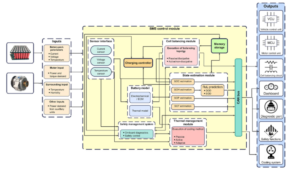
Image Source: Encyclopedia.pub
A good battery management system (BMS) needs hardware components that work together to monitor, protect, and optimize battery performance. These components act as the system’s eyes and ears. They collect vital data that helps make smart decisions about battery safety and longevity.
Voltage Monitoring Circuits
Voltage monitoring circuits track the potential difference between individual cells in a battery pack. These circuits measure so the BMS can keep proper levels for safety and efficiency. My experience shows that accurate voltage monitoring lets the BMS perform essential cell balancing, which ensures even charge distribution in all cells.voltage with high precision
These monitoring devices calculate the State of Charge (SOC) and protect against harmful overcharging or deep discharge conditions. Most voltage monitoring circuits use specialized analog-to-digital converters that can measure multiple cell voltages at once with great accuracy.
Differential operational amplifiers often measure individual cell voltages. These amplifiers compare voltages between two terminals—inverting and non-inverting—and amplify the difference. The BMS uses these precise voltage readings to make control decisions.
Current Sensing Modules
Current sensing modules measure electricity flowing in and out of the battery pack. They work with the primary fuse to protect the entire pack from overcurrent. Current monitoring helps:
- Calculate State of Charge through coulomb counting
- Detect problems like over-current or short-circuits
- Check battery health and remaining capacity
- Keep operations within the battery’s safe limits
Modern battery management systems mainly use two technologies for current sensing:
Shunt resistors range from 25 μΩ to 100 μΩ in EV applications and provide excellent linearity and accuracy. These low-resistance parts handle high currents while keeping power loss minimal. Hall-effect sensors offer a different approach. They isolate the sensing circuit from the current path and measure both AC and DC currents without direct electrical connection.
Electric vehicles need different current levels for charging and discharging. Charging currents usually range from 0A to 100A, while discharge currents can reach 2,000A. The current sensing module handles this wide range accurately.
Temperature Sensors and Thermal Management Units
Temperature sensors round out the essential components in a complete BMS by watching thermal conditions throughout the battery pack. Batteries create heat during operation, and temperature affects their efficiency a lot. This makes thermal monitoring crucial for best performance.
Too much heat can cause thermal runaway—a dangerous situation that might lead to battery failure or fires. Thermocouples or negative temperature coefficient (NTC) thermistors sit at key spots in the battery pack to prevent this.
BMS designs often use NTC thermistors because they’re sensitive, accurate, cost-effective, and work well in different physical setups. These parts show a non-linear exponential decreasing resistance/temperature pattern that the BMS measures through voltage divider networks.
Large battery packs need multiple temperature sensors because heat doesn’t spread evenly. Sensor data helps the BMS take action—like turning on cooling systems or adjusting charge and discharge rates—to keep temperatures safe.
Lithium-ion batteries work best between 15°C and 35°C. The BMS works hard to keep the pack in this range whatever the outside temperature.
Battery Management System Architectures Explained
A battery management system’s architecture defines how its components connect and work together in the battery pack. The design choices affect system reliability, scalability, and performance capabilities. Battery systems have become more complex, making architecture selection crucial to ensure safe and optimal operation.
Centralized BMS Design
A centralized battery management system uses a single controller to monitor all cells in the battery pack. The main control unit connects directly to each battery cell or module through dedicated wiring harnesses. This central unit handles voltage monitoring, temperature sensing, balancing, and protection functions.
Centralized designs excel at simplicity and cost savings. The single-controller approach makes them compact and cheaper than other configurations. Many smaller battery systems with few cells use centralized BMS topologies. Electric bikes, scooters, and light electric vehicles are good examples.
These designs come with several limitations:
- Large battery packs need complex wiring to each cell
- More ports and connections make maintenance and troubleshooting harder
- Battery capacity cannot easily scale up
- The central controller becomes a single point of failure—its malfunction affects the whole system
Centralized designs remain popular where simple, economical battery management works best. The Tesla Model S uses a centralized BMS topology. A single controller processes battery cell data to manage charge and discharge cycles efficiently.
Modular and Distributed BMS Topologies
Modular and distributed architectures split monitoring and control functions between multiple units. These approaches work differently in their implementation and capabilities.
Modular BMS systems divide into several similar modules. Each module watches over its assigned battery cells through dedicated wiring. A main controller often coordinates these modules’ activities. The system becomes easier to troubleshoot and maintain. Battery packs can grow larger without much difficulty. This flexibility costs more than centralized designs.
Distributed BMS architectures take decentralization further. Control boards sit directly on the monitored cells or modules. This setup needs minimal sensor and communication wires between modules. The system keeps working even if one component fails because each part functions independently. The BMW i3 uses a modular BMS architecture. Its battery pack has distinct modules with independent BMS units that technicians can service separately.
Both designs work well when systems need to scale or stay reliable. Distributed systems shine in high-voltage applications. Grid energy storage systems, aerospace applications, and electric vehicles need this fault tolerance.
Primary/Subordinate BMS Systems
Primary/subordinate BMS architecture (also called master/slave) combines centralized and modular design elements. A primary controller works with multiple subordinate modules.
This design looks like modular topology but works differently. Subordinate modules send measurement data to the master module. They don’t do much computation or control. The primary controller handles complex calculations, control decisions, and external communications. Simpler subordinate modules cost less and need less overhead.
The architecture balances centralized simplicity with modular flexibility. It costs less than fully modular systems because subordinate modules do less work. The system can still scale reasonably well while keeping individual components simple.
Some applications work best with this balanced approach. It performs better than centralized systems without distributed architecture’s full cost. The Nissan Leaf shows how distributed BMS topology works. Individual controllers manage each battery module. This improves system efficiency and safety through precise module-level management.
Engineers choose BMS architecture based on their application needs, battery size, redundancy requirements, and budget. Each design offers unique benefits and trade-offs that must match system requirements.
Materials and Methods for BMS Development
A functional battery management system needs carefully chosen specialized hardware and software components. High-performance microcontrollers, reliable communication protocols, and resilient switching elements are the foundations of effective BMS solutions.
Microcontroller Units (MCUs) and Integrated Circuits (ICs)
Every battery management system has a microcontroller unit that works as its computational brain. These specialized processors manage critical BMS functions like cell monitoring, balancing algorithms, and safety protection mechanisms. MCU selection depends on the application’s specific needs.
Automotive and industrial applications that need advanced performance and safety compliance use microcontrollers like NXP’s MPC5775B and MPC5775E. These offer . The MCUs’ critical features include hardware security modules and temperature ranges from -40°C to 125°C, which makes them perfect for tough environments.ASIL D support with 4 MB of flash memory and operating speeds of 220-264 MHz
MCU requirements vary based on the battery system’s complexity:
- Low-complexity systems: Small BMS use cost-optimized MCUs with low power consumption. They combine multiple functions to cut overall system cost
- Medium-complexity systems: Systems with 1-6 cells work best with MCUs that support complete communication interfaces including I2C, SPI, and UART
- High-complexity systems: 6-23 cell applications (power tools, e-mobility) need MCUs with high performance and better peripherals
Battery management ICs work alongside MCUs by providing specialized functionality. To cite an instance, see Infineon’s battery management ICs that monitor and balance up to 12 cells in lithium-ion battery packs. They measure cell voltage, temperature, and enable isolated communication to the main controller. These ICs work well in safety-relevant applications up to ASIL-D and comply with ISO 26262 standards.
CAN Bus Communication Protocols
CAN Bus stands as the most popular communication protocol for battery management systems, especially when you have automotive applications. This protocol runs at data speeds of 250-500 Kbps and uses extended frame identifiers to ensure reliable data flows between BMS components.
CAN Bus protocol in BMS applications follows specific implementations:
- Uses 29-bit identifiers in extended frame format
- Has prioritized message structures with designated source and destination addresses
- Supports multi-master communication where different nodes can transmit on the same bus
- Includes extensive error detection and correction mechanisms
The protocol’s multi-master design removes the need for a dedicated master node. This creates a more stable and fault-tolerant system that keeps working even if individual nodes fail. This feature makes CAN Bus ideal for safety-critical applications where communication reliability matters most.
BMS development teams must review speed requirements, physical distance between components, multi-drop support, cost, and power consumption when choosing a communication protocol. CAN Bus usually becomes the best choice for projects that need high reliability in electromagnetically noisy environments.
Power MOSFETs for Switching and Protection
Power MOSFETs control charge and discharge pathways in battery management systems while protecting against fault conditions. These semiconductor devices connect in series between the battery pack and output load, with dedicated ICs controlling their operation.
BMS applications use two main MOSFET types:
- N-channel MOSFETs: These devices work more efficiently due to their lower on-resistance (RDS(on)) but need more complex driving circuits
- P-channel MOSFETs: They have simpler driving requirements but less efficiency than N-channel alternatives due to higher on-resistance
BMS implementation requires careful MOSFET selection based on key parameters. Voltage rating must handle maximum voltage conditions, while current rating should exceed the highest expected current for safe operation. Low on-resistance values help reduce power losses and boost efficiency during operation.
MOSFET selection heavily depends on thermal management. MOSFETs in BMS applications should stay below 65°C in normal environments. PCB design can help by maximizing copper area and adding dissipation vias near MOSFET mounting spots to improve heat dissipation.
Battery Protection Mechanisms in BMS Battery Systems
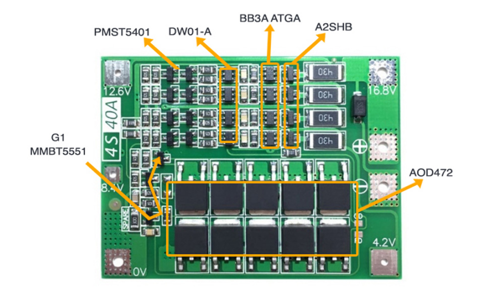
Image Source: Circuit Digest
Safety is the top priority in lithium-ion battery applications. Protection mechanisms act as vital safeguards against potential risks. A well-laid-out battery management system uses multiple protection layers to keep batteries operating safely in all conditions.
Over-voltage and Under-voltage Protection
The battery management system’s voltage protection circuits monitor pack voltage and individual cell voltages continuously. My experience shows that precise voltage thresholds are significant to maintain battery health and safety.
The BMS monitors voltages every millisecond to protect against over-voltage. The system disconnects the charging circuit or reduces charging current immediately when it detects excessive voltage. This protection matters because too much into the negative electrode. This migration can deform the positive electrode’s structure and create dangerous dendrite growth.overcharging can cause lithium ions to migrate
Under-voltage protection works as a backup safeguard that stops batteries from discharging below key thresholds—usually 2.5V or 3.2V based on cell chemistry. This protection stops deep discharge conditions that cause permanent damage and capacity loss. The BMS cuts off the load to stop further discharge when voltage drops below the preset threshold.
Over-current and Short-circuit Protection
The BMS offers two connected types of current protection: overcurrent and short-circuit protection. Immediate current monitoring helps the system detect problems before they become dangerous situations.
The system’s overcurrent protection watches current flow and triggers protective measures when it exceeds thresholds. Most systems disconnect the discharge FETs through hardware instead of software when they detect excessive current. Software responses aren’t fast enough to prevent damage.
Short-circuit protection needs ultra-fast response times between 250-500 microseconds. Short circuits create a direct path with minimal resistance that causes sudden current surges. The BMS must cut off the battery instantly to prevent catastrophic failures. The number of MOSFETs needs proper sizing based on potential short-circuit current. One pair of FETs might fail, but four pairs can effectively stop dangerous current flow.
Thermal Runaway Prevention Strategies
Thermal runaway is one of the most dangerous ways lithium-ion systems can fail. This chain reaction of heat-producing events needs detailed monitoring through carefully placed temperature sensors.
My thermal runaway prevention strategy uses multiple protection layers:
- Active monitoring: The BMS tracks cell-level temperature data using NTC thermistors between cells, on power components, and the BMS board
- Early detection: Off-gas monitoring warns early by detecting gas release before thermal events happen
- Protective disconnection: The BMS trips the inline breaker to disconnect the battery when it detects dangerous temperature increases
A detailed approach that combines exact monitoring technologies, warning systems, and automated protection circuits ensures lithium battery systems’ safe operation in all conditions.
Capacity Management and Cell Balancing Techniques
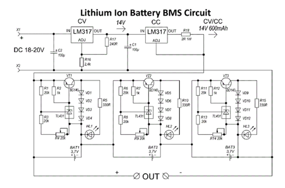
Image Source: Hackatronic
Battery packs often face cell imbalance issues as individual cells show different charge levels over time. Manufacturing differences, self-discharge rates, and operating conditions cause these variations. The difference between cells can range from based on usage and age. Cell balancing helps manage capacity and maximizes the battery’s performance and life.3% to 6%
Passive Balancing Using Shunt Resistors
Passive balancing makes cells equal by converting excess energy from higher-charged cells into heat through resistors. Engineers use two main approaches: fixed shunt resistors and switched shunt resistors. Switched shunt systems use transistors that control when resistors work. The BMS can then discharge specific cells with higher voltage until all cells balance out.
Passive balancing remains popular because it’s simple and affordable. The basic circuit design costs less than complex alternatives. Notwithstanding that, this method has clear drawbacks. Higher-charged cells waste all their extra energy as heat, which reduces efficiency. The system also needs extra cooling features, especially for high-power uses.
Active Balancing with Energy Redistribution
Active balancing works differently from passive methods by moving energy between cells instead of wasting it. This approach transfers charge from higher to lower-charged cells. The system runtime improves because it uses the battery pack’s full capacity.
Active balancing comes in several forms:
- Capacitive balancing: Capacitors store and move energy between cells
- Inductive balancing: Inductors move energy while controlled switches manage the flow
- Transformer-based: Transformers transfer energy between cells faster using fewer switches
Active balancing saves about 4.15% energy in each charge/discharge cycle across the battery pack. The system helps weaker cells during discharge, which extends the pack’s runtime and usable capacity.
State of Charge (SOC) and State of Health (SOH) Estimation
Proper capacity management needs accurate SOC and SOH measurements. SOC shows remaining capacity as a percentage from 0-100%. SOH indicates how well the battery works compared to its original condition.
The basic Coulomb Counting (CC) algorithm finds SOC by adding up current measurements over time. Its accuracy depends on how precise the sensors are. Modern methods like Kalman filtering and AI can estimate with less than 2.05% Mean Absolute Percentage Error.
SOH estimation combines several measurement techniques because no single method gives perfect results. Batteries lose capacity and gain internal resistance as they age. A battery might lose 20% capacity while its internal resistance grows to 160% of the original value. Good SOH estimates warn about battery wear and tell you when it needs replacement.
Failure Modes and Limitations of Battery Management Systems
Modern battery management systems have sophisticated designs, yet these critical components can still fail and compromise safety and performance. than other system failures, and technicians find them hard to diagnose and fix.BMS failures happen more often
Common Failure Scenarios in BMS
BMS systems fail most often due to voltage detection problems that can create dangerous overcharging conditions. Research shows lithium iron phosphate batteries emit smoke when overcharged beyond 5V. Ternary batteries might explode in similar conditions. The biggest problem occurs when Hall sensors stop working properly. This prevents accurate current measurement and SOC calculation. Temperature detection failures create equally dangerous situations – battery life at 45°C drops to half of what it lasts at 25°C.
EMC issues can break the connection between BMS components and cause system malfunctions. Battery systems that experience deformation or leakage face insulation monitoring failures. These failures might create electric shock hazards.
Impact of Sensor Failures on Battery Safety
Voltage, current, and temperature signals are the foundations of BMS functions like state estimation and fault diagnosis. Failed sensors leave the system working with wrong or incomplete data. Systems can detect voltage sensor faults and determine their size but struggle to pinpoint their exact nature.
Each fault diagnosis method works differently. Unscented Kalman filters can detect and isolate faults but can’t determine their size and shape. PD descriptor observer-based methods handle more sensor faults, including high-frequency and low-frequency problems.
Limitations in High Voltage Applications
High voltage BMS systems need extra protection mechanisms to solve the problems of safety. These include protection against overvoltage, undervoltage, overcurrent, and isolation faults. High voltage batteries can cause electrocution, fire, and thermal runaway if not managed properly.
Current measurements in BMS might not warn about upcoming failures quickly enough. Temperature and voltage indicators lag behind actual safety issues. Warning signs sometimes appear only when batteries are about to catch fire or are already burning.
Emerging Trends in Lithium Battery Management Systems
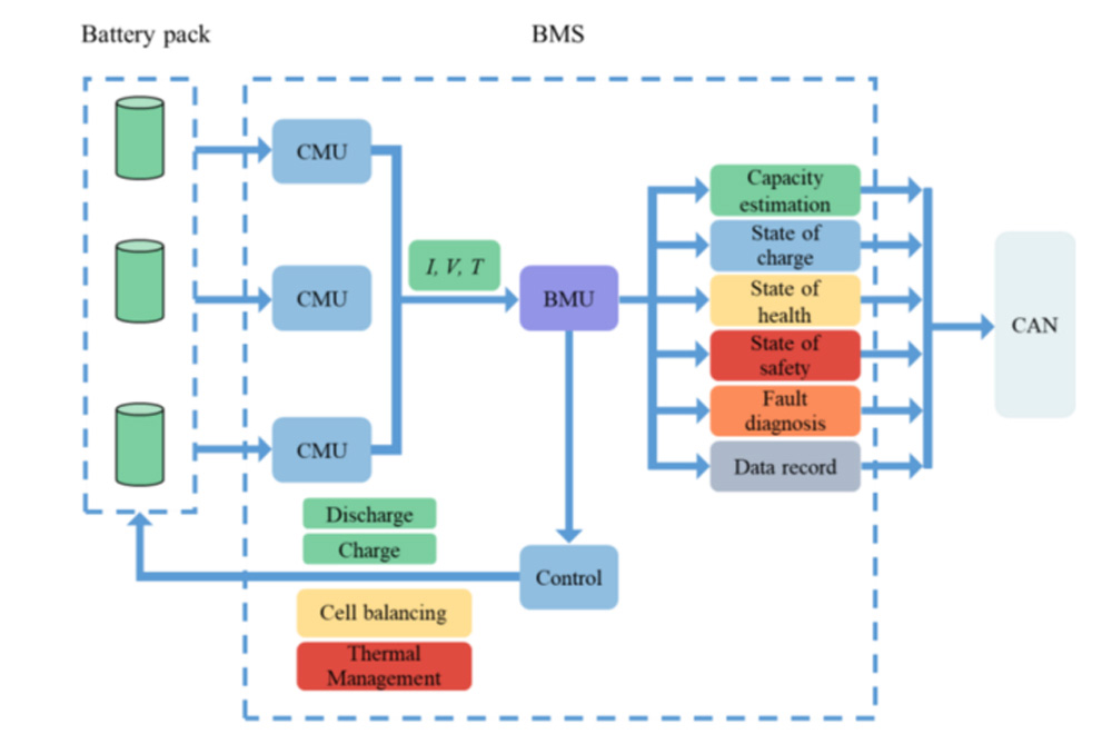
Image Source: MDPI
Battery management systems are changing faster than ever, and three major technological changes are about to reshape how these vital systems work and connect with their surroundings.
AI and Machine Learning for Predictive Maintenance
AI and machine learning are bringing new capabilities to BMS through advanced predictive analytics. These technologies look at live data from batteries and can estimate significant parameters like State of Charge (SOC) and State of Health (SOH) with . AI algorithms do more than just monitor – they can predict battery performance in different conditions by studying usage patterns and environmental factors.error rates below 2.05%
AI-powered systems analyze data continuously to figure out the best charging protocols. They consider the battery’s age, temperature, and how it’s used to reduce cell stress and make batteries last longer. This marks a change from fixing problems after they happen to stopping them before they start.
Wireless BMS Architectures
Wireless battery management systems (wBMS) get rid of complex wiring between battery modules. This new approach brings several benefits: less weight, smaller size, easier maintenance, and better-synchronized sensor measurements.
SmartMesh technology in wBMS creates networks that can fix themselves with different paths and frequencies. Messages route around obstacles and handle interference well. The system syncs each node’s time within microseconds, which means measurements from different spots can be compared precisely. This precise timing is a big deal as it means that SOC and SOH calculations are much better.
Integration with Smart Grids and IoT Devices
IoT capabilities meet battery management systems to create constant data streams from batteries everywhere. This gives us a clear picture of how they perform and wear down. The connection makes it possible to watch important measurements and predict what might happen next.
Smart grid applications with BMS can cut energy use by 10% to 30% in commercial buildings. These combined systems make two-way talks between energy storage and grid operators possible through standard protocols like IEC 61850 and DNP3. Buildings have moved from just using power to helping manage the grid actively.
Conclusion
Battery management systems are the critical intelligence behind modern battery technologies, especially when you have lithium-ion chemistries that just need constant monitoring for safety. In this piece, we got into how BMS technology protects batteries from dangerous conditions while optimizing their performance and extending their lifespan.
BMS architectures have grown from centralized to distributed systems, showing how this technology adapts to complex energy storage needs. Safety features like over-voltage, under-voltage, and thermal runaway protection create multiple defense layers to prevent battery failures. Both passive and active cell balancing techniques substantially extend battery life by maintaining uniform charge distribution.
The future of BMS development points to groundbreaking advances with artificial intelligence, wireless architectures, and smart grid integration. These technologies will change battery management from basic protection circuits to predictive systems that spot failures before they happen. Battery storage’s expanding role in renewable energy systems, electric vehicles, and consumer electronics makes these advances vital.
Your BMS selection should match your application’s voltage requirements, current handling capacity, and thermal management needs. Our team at Large Power can help you find custom battery solutions that fit your specifications. The fundamentals covered here are the foundations of making smart choices about your battery system design.
The battery management system works as both a guardian and optimizer. It protects valuable battery assets while maximizing their performance. As batteries advance with higher energy densities and faster charging capabilities, management systems must keep pace to ensure safety, reliability, and peak performance remain top priorities.
FAQs
Q1. What are the main functions of a Battery Management System (BMS)? A Battery Management System monitors voltage, current, and temperature of battery cells, calculates state of charge and health, performs cell balancing, manages thermal conditions, and provides protection against unsafe operating conditions.
Q2. How does a BMS protect batteries from overcharging and deep discharge? A BMS continuously monitors cell voltages and disconnects the charging circuit or reduces charging current if voltages exceed safe limits. For deep discharge protection, it disconnects the load when voltages drop below a preset threshold to prevent permanent damage.
Q3. What are the advantages of a distributed BMS architecture? Distributed BMS architectures offer enhanced redundancy, simplified wiring, easier troubleshooting, and better scalability for large battery packs. They allow independent functioning of modules even if one component fails.
Q4. How does cell balancing improve battery performance? Cell balancing equalizes charge levels across individual cells, preventing weaker cells from limiting overall pack performance. This extends battery lifespan, maximizes usable capacity, and improves overall efficiency of the battery system.
Q5. What emerging technologies are transforming Battery Management Systems? Artificial intelligence and machine learning are enabling more accurate predictive maintenance. Wireless BMS architectures are reducing complexity and weight. Integration with smart grids and IoT devices is allowing for more dynamic energy management and grid participation.
Need BMS support for a custom lithium battery pack? Large Power can design custom BMS and PCM protection, cell balancing, communication protocols, and safety validation around your device requirements. Request a custom battery solution.


