

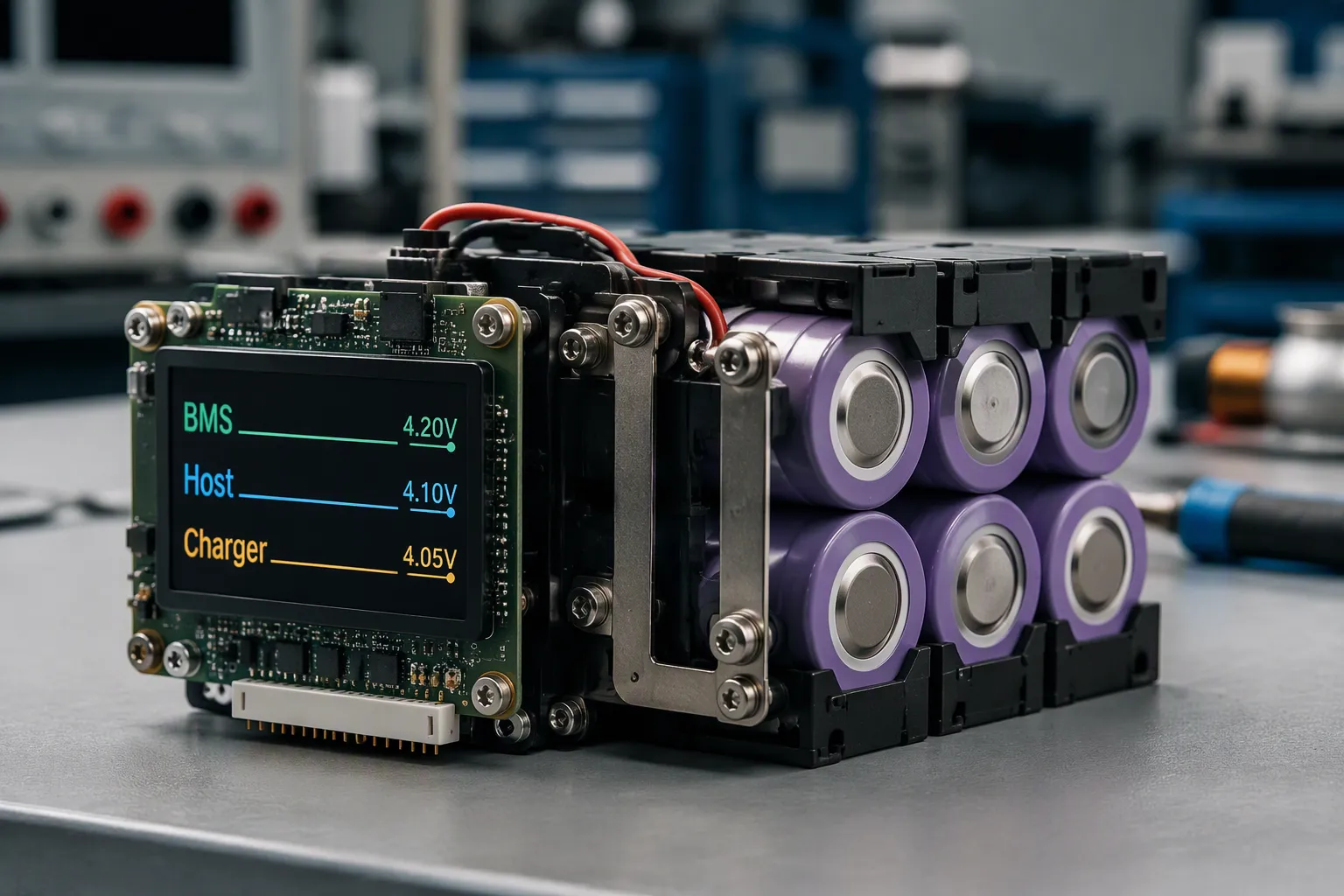
Protection coordination means keeping normal operation inside the approved cell and pack limits while defining a safe response to faults. It is not a universal rule that the charger always acts first, the host second and the BMS last. A short circuit may require immediate hardware protection before the host can respond.
Part 1: Separate Operating Control from Fault Protection
1.1 Define the normal operating envelope
Start with the approved cell specifications, series and parallel configuration, thermal design and load profile. Record permitted charge and discharge conditions separately. Pack current, cell-group voltage and sensor temperature are different quantities and need separate limits.
The charger should regulate within the approved charging envelope. During ordinary discharge, the host should reduce load, alarm or shut down before an avoidable undervoltage trip. This does not justify delaying urgent protection.
1.2 Assign each protective function
A PCM or BMS may disconnect charging, discharging or both, depending on its circuit. Monitoring, balancing, communication and secondary protection are implementation-dependent. Temperature sensing at selected locations does not mean every cell temperature is measured.
Review the actual BMS and PCM architecture rather than inferring functions from its name.
Part 2: Build a Threshold Coordination Matrix
2.1 Include tolerances and measurement locations
For each condition, document normal control limits, warning levels, protection thresholds, detection delay, recovery threshold and responsible controller. Include guaranteed measurement accuracy, configuration resolution, drift and switching tolerances. Use minimum and maximum limits, not typical values alone.
Charger output voltage is not necessarily the voltage sensed at the cell terminals. Wiring, connections and switching devices contribute current-dependent drops. A pack-level voltage reading can conceal one weak series group.
2.2 Check timing and hysteresis
Compare startup and motor pulses with the cell, MOSFET, fuse and interconnect capabilities. Do not increase overcurrent delay merely to avoid nuisance trips. Confirm that every component remains within its permitted electrical and thermal stress throughout the event.
Hysteresis and recovery conditions should prevent repeated on/off cycling near a boundary. Determine whether recovery requires charger connection, load removal, a command, cooling or service intervention.
Part 3: Coordinate the Charger and Host
3.1 Charging and discharge need different logic
During charging, check regulator tolerances against cell limits and protective thresholds. During discharge, ensure the host has sufficient time and energy for its intended controlled stop. There is no single ascending voltage hierarchy that describes both cases.
Changing from NMC to LiFePO4, LCO or LMO is not just a threshold substitution. Reassess cell limits, usable voltage range, current capability and system behavior for the selected part number.
3.2 Define communications failures
Specify timeout detection, stale-data handling and safe fallback behavior. A safe response may involve load reduction, an alarm, a controlled stop or independent power continuity measures. Medical essential-performance requirements must come from the device risk analysis; an automatic shutdown is not always the safest outcome.

Part 4: Validate Faults and Recovery
4.1 Test realistic operating corners
Use controlled equipment and qualified personnel to test relevant voltage, load, state-of-charge and temperature corners. Capture cell-group voltages, pack current, switching status, host response and timestamps. Include aged or high-resistance conditions where the validation plan requires them.
Simulate communication loss, sensor faults and abnormal charger behavior using a safe fault-injection plan. Do not perform uncontrolled short circuits or bypass protective circuits on an assembled pack.
4.2 Control configuration changes
Keep the approved protection configuration under revision control. Changes to cells, firmware, charger, sensors or host loads require an impact assessment that defines the necessary regression tests. Not every unrelated firmware change requires repeating every test.
Part 5: OEM Release Checklist
Approved cell and pack limits and their source documents.
Threshold, tolerance, delay, hysteresis and recovery matrix.
Startup, pulse-load and sustained-load evidence.
Host warnings, shutdown timing and remaining-energy margin.
Communications timeout and fault response records.
Configuration revision, test setup and release approval.
For a custom project, provide the load profile, charger information and host behavior through the custom battery solution inquiry.
FAQ
Should the BMS always act last?
No. Normal control should avoid unnecessary protection trips, but short circuits and other urgent faults may require immediate independent intervention.
Can I copy thresholds from another pack of the same chemistry?
No. The cell model, protection hardware, thermal arrangement and application determine the settings.
Does communication replace hardware protection?
No. Communications can coordinate normal behavior and report faults, but its availability and failure modes must be considered separately.
Where can I check how thresholds and recovery are implemented?
Use the selected protection IC documentation. For example, the Texas Instruments BQ76952 documentation describes configurable protection and recovery functions. It is a component-specific reference, not a recommended configuration for every pack.


