

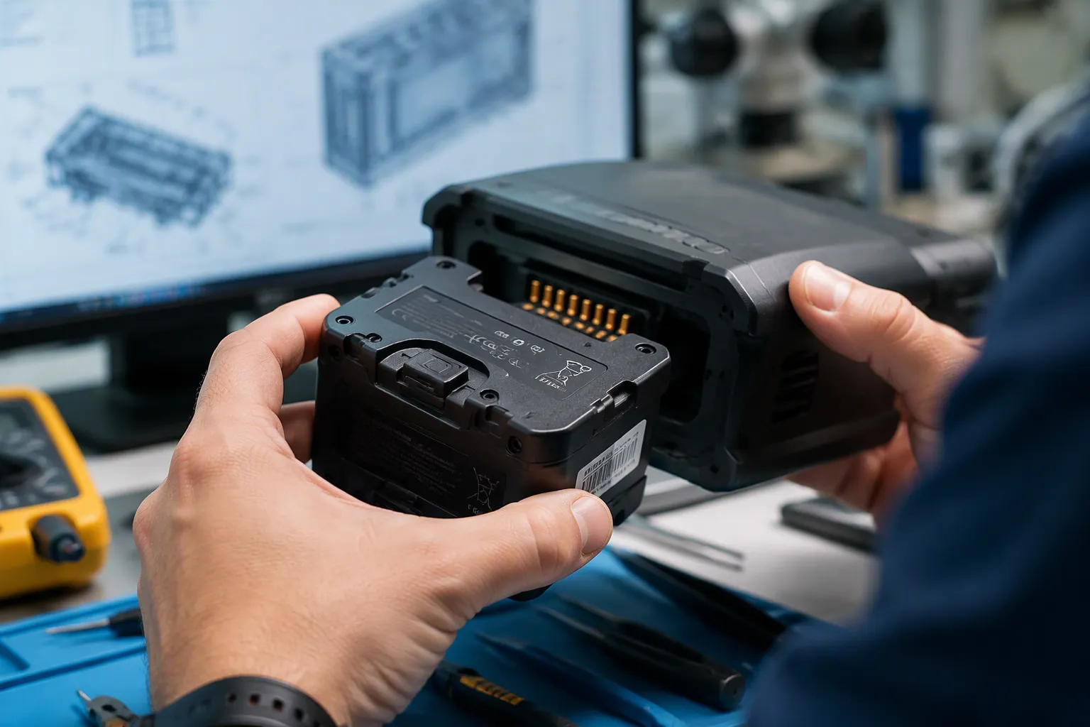
A removable battery interface combines mechanical retention, electrical contact and host control. A pack that fits its bay can still fail through misalignment, wear, contact bounce or an undefined insertion sequence. OEM validation should evaluate the assembled interface over its intended service life.
Part 1: Define the Replacement Scenario
1.1 Separate removable from hot-swappable
A removable pack may require the equipment to be switched off before replacement. Hot swapping requires an explicitly validated power architecture and sequence. A latch or blind-mate connector alone does not provide uninterrupted operation.
1.2 Specify users and environment
Identify who replaces the pack, which tools are permitted, expected gloves or handling constraints, and exposure to dirt, fluids or vibration. Medical, robotics and field equipment may need different interface behavior even at the same voltage.
Part 2: Control Mechanical Fit and Retention
2.1 Build the tolerance stack
Consider pack dimensions, rails, connector placement, molded parts, mounting deflection and cell expansion where relevant. Guidance features should align the mating parts without forcing electrical contacts to correct major misalignment.
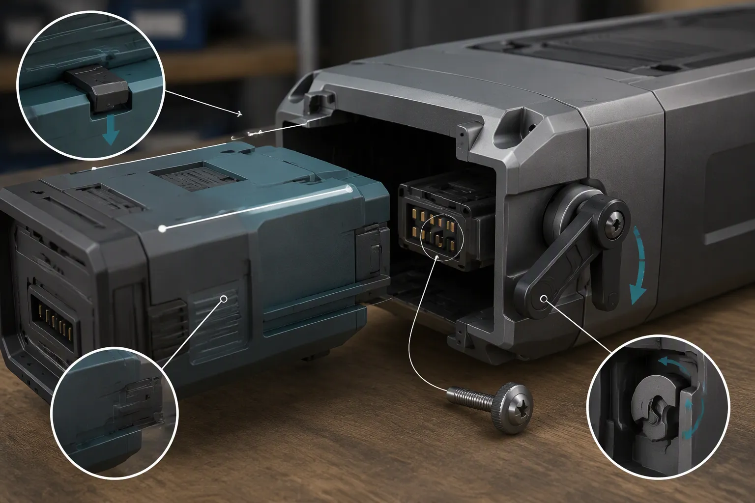
2.2 Validate latching and removal
Define insertion force, retention force, release force and clear engagement feedback. Evaluate incomplete engagement and foreseeable incorrect insertion. Retention requirements come from actual handling and transport conditions, not an assumed universal latch strength.
Part 3: Define Contact and Signal Behavior
3.1 Specify the mating sequence
Where sequencing is required, define which contacts establish or break first and verify it across tolerances, insertion speeds and wear. Do not assume power, ground, identification and communication pins mate in a predictable order simply because their nominal lengths differ.
3.2 Control electrical transients
Evaluate inrush, contact bounce, reverse connection prevention and possible arcing under the permitted operating state. Pre-charge or controlled switching may be necessary for some architectures, but the solution depends on voltage, capacitance, current and connector capability.
Coordinate pack-enable and fault behavior with the BMS and PCM design. Do not use software recognition as the only barrier against a hazardous misconnection.
Part 4: Test Wear and Environmental Exposure
4.1 Use representative insertion cycling
Agree on cycle count and handling conditions from the intended service life and connector data. Inspect contact wear, retention, alignment and electrical resistance at defined intervals. A component rating does not automatically validate the complete battery bay.
4.2 Measure under load
Track voltage drop and temperature rise through the complete mating path. Evaluate vibration or movement in the installed state and contamination appropriate to the application. Test ingress protection in the specified installed configuration; an enclosure rating does not automatically apply while the pack is removed.
Part 5: Freeze the Interface Contract
Controlled pack and bay drawings with tolerances.
Connector part numbers, pinout, polarity and mating sequence.
Permitted replacement state and user instructions.
Retention and insertion-cycle acceptance criteria.
Electrical, thermal and environmental evidence.
Host recognition, enable, removal and fault-response records.
FAQ
Can a removable pack be unplugged under load?
Only when the connector and system have been designed and validated for that operation.
Is the connector cycle rating enough?
No. Validate the mounted connector, rails, latch and complete electrical path together.
What should an OEM provide?
Share the battery-bay CAD, replacement scenario and electrical requirements through the custom battery project inquiry.


