

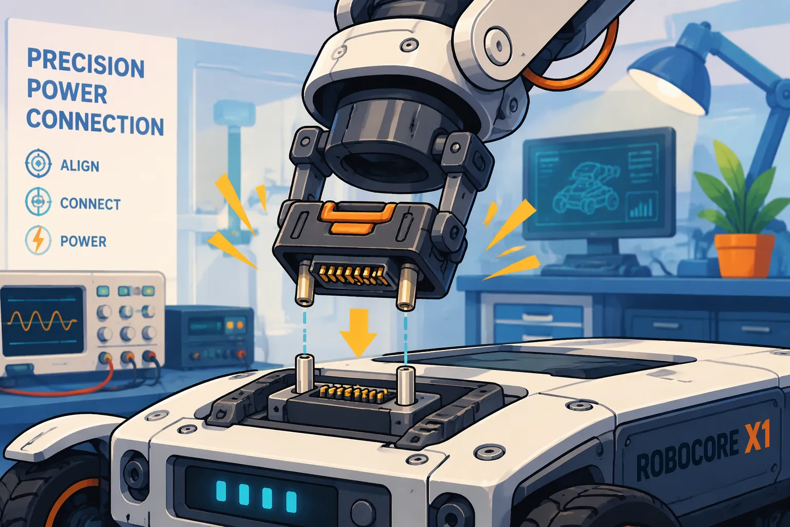
Quick Answer: Specify a blind-mate connector using the robot’s worst-case docking offsets, required contact sequence and expected mating cycles. Validate those requirements in the actual rails, latch and enclosure. If the pack can be connected while energized, verify partial insertion and the host’s power-enable behavior separately.
A blind-mate connector is a plug-and-receptacle interface built to connect when the mating faces can’t be seen or lined up by hand.
This article treats alignment, contact sequence, and mating life as linked design variables for lithium battery packs, not separate specs. Each main section ends with application fit, compliance, and cost. The focus stays on robot-specific docking tolerance, partial insertion, and validation, rather than a general removable-pack interface.
Key Takeaways
Guide features and float mounts fix small misalignments, but you must measure the real tolerance stack.
Pins of different lengths set the order in which contacts are made: ground first, then power, then signal, so hot-plugging stays safe.
Test a partial insertion to make sure no power flows and no BMS fault latches when docking stops halfway.
Match the connector’s mating life to your battery chemistry: LiFePO4 packs need higher cycle ratings than NMC packs.
Test connectors with your own docking fixture and duty-cycle test, not just datasheet ratings.
Part1: Alignment in Blind-Mate Battery Connectors for Robots
1.1 Guide Features and Float Mounts
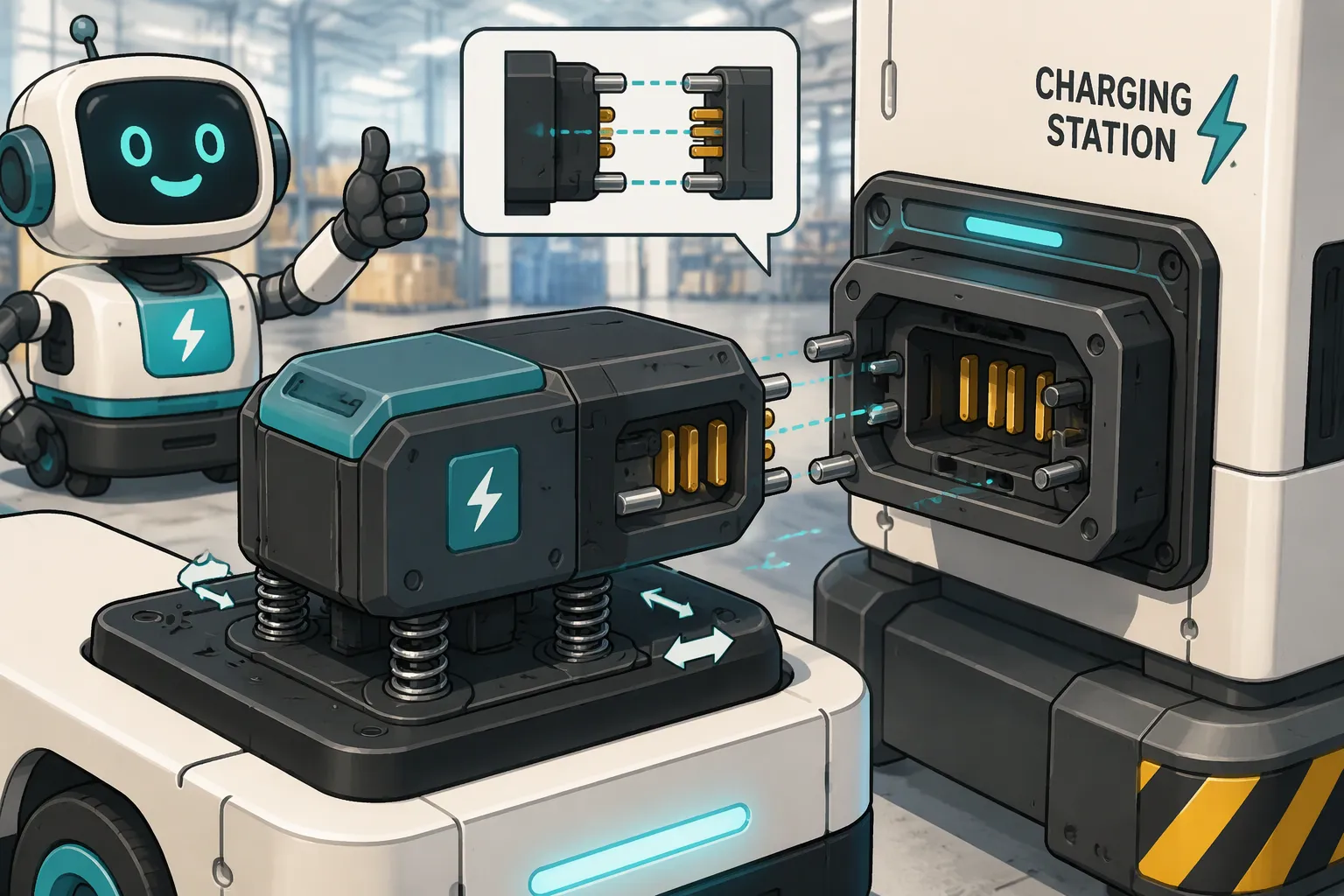
Alignment begins before any contact touches. Chamfers and lead-in ramps on the plug and receptacle guide the two halves together as they come close. A wide lead-in turns a big side-to-side offset into a small corrective motion. Guide pins and guide slots take over once the faces are near. These features absorb angle error first, then side-to-side error, and they center the interface before the pins engage.
Floating connector series add a second layer of correction. The connector body mounts on a spring-loaded or sliding base. This base moves a few tenths of a millimeter in any direction and lets the connector find its mate. Float mounts work well in tight spaces, such as a battery pack tucked behind a robot’s rear panel. The float travel must be larger than the leftover misalignment of the docking approach. If not, the connector bottoms out and the guide features carry the full load.
Warehouse AMR and AGV charging docks depend on this combination every day. A fleet vehicle backs into a dock with centimeter-level repeatability, and the guide features close the remaining gap. Medical service robots need gentler engagement, because a hard stop can disturb a payload. Security patrol units dock outdoors, where thermal expansion shifts the mount across the day. NASA’s robot-driven blind-mate interface shows the same principle at a larger scale: a robotic arm positions the halves, and the interface completes the structural and electrical connection without human hands.
1.2 Tolerance Stack-Up and Docking Validation
Alignment error builds up across three bodies: the robot chassis, the battery pack, and the connector mount. Each part carries its own dimensional tolerance, and each joint adds stack-up. Most blind-mate connectors still require relatively tight alignment tolerances, even with float mounts. A loose chassis tolerance can use up the entire float budget before the connector sees any error.
Validation must measure the real stack, not the nominal drawing. Engineers should build the docking fixture, mount the actual pack, and record lateral and angular offset at first contact across many approach cycles. This test exposes the worst-case corner, where chassis sag, pack sag, and mount error line up in the same direction.
Application fit drives the choice between tight and loose alignment designs. LiFePO4 packs suit high-cycle fleet docking, where repeatable alignment protects contact life over thousands of mates. NMC packs suit energy-dense platforms, where pack mass and stiffness change the stack-up. Compliance matters here: IEC 62133-2 covers the safety of lithium secondary cells and batteries in portable applications, UL 2054 covers household and commercial battery packs, and ISO 3691-4 addresses driverless industrial trucks and their systems. Tighter alignment costs more in machining and fixture precision. Looser alignment saves cost but shifts stress onto contacts and guide features. The right balance depends on dock repeatability, fleet size, and service access.
Part2: Contact Sequence for Safe Power Transfer
2.1 Staggered Pins and Hot-Plug Safety
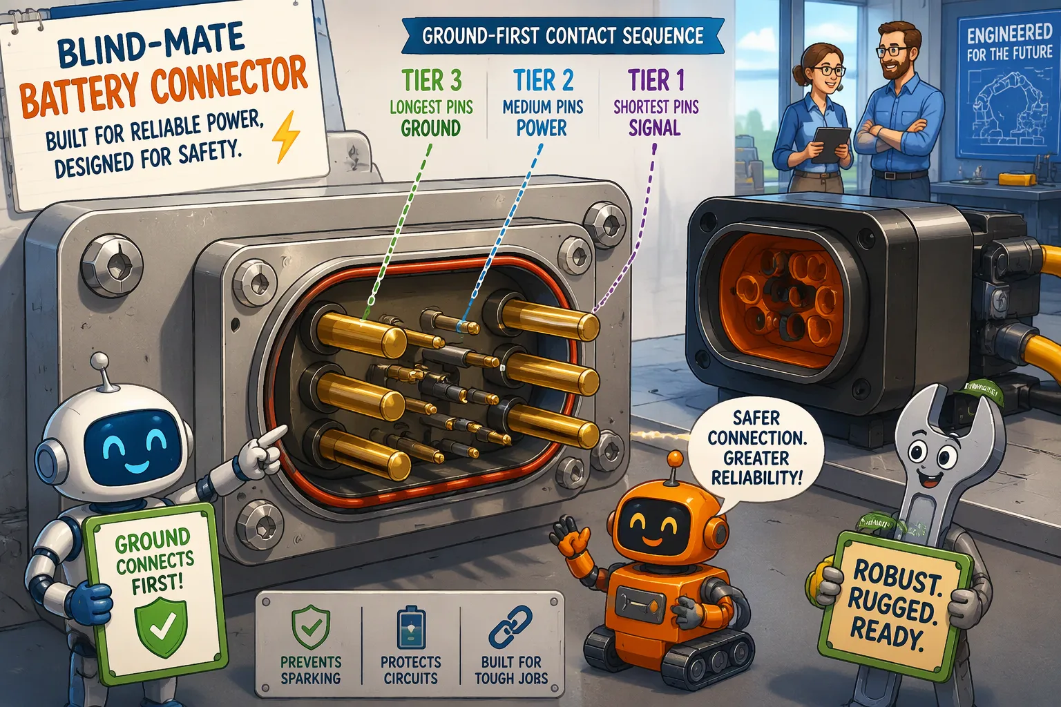
Contact sequence is a mechanical plan built into pin length. A typical layout uses three tiers. Pre-contact pins are the longest and touch first; they carry ground and low-level signal so the pack and the robot share a reference before any current flows. Main power pins sit in the middle tier and close the high-current path. Post-contact pins are the shortest and close last; they carry status, enable, or interlock lines that tell the system the mate is complete.
Engineers should confirm this order on the actual connector, not assume it. Pin lengths vary by series, and some designs reverse the tiers or place signal pins in a separate housing. Blind mating and energized insertion are also separate problems. A connector can guide itself together perfectly and still arc if the power pins close before ground.
Hot-plug safety depends on that ground-first order. When a robot docks with the pack energized, the pre-contact ground pin equalizes potential before the power pins meet. This step limits arcing at the power contacts and controls the inrush current that flows into the pack’s input capacitance. Without it, a fast voltage step can trip the battery management system on overcurrent or short-circuit protection, and the dock fails even though the mechanical mate succeeded. The same logic runs in reverse during unmating: ground must break last, so the enable line drops first and the system shuts the power path down cleanly. A BMS that latches a fault on an arcing event will hold the pack offline until a service reset, which is costly in a fleet. Designers who want background on protection thresholds can review BMS and PCM fundamentals.
2.2 Partial Insertion and Sequence Verification
A robot sometimes stops mid-dock. The drive stalls, an obstacle blocks the approach, or the dock loses alignment at the last centimeter. In that state, the pre-contact pins may touch while the power pins stay open. The pack sees ground and signal but no main path, and the robot reads an incomplete mate.
Good sequence design turns that state into a detectable signal. The post-contact enable line stays open until full insertion, so the robot’s controller sees “not ready” and can retract and retry. Some designs add a dedicated mate-detect pin at the shortest tier for the same purpose. Verification belongs in the docking fixture test: engineers should command a partial approach, hold position, and confirm that no power flows and no BMS fault latches.
Application fit shapes the pin count. LiFePO4 fleet packs in warehouse AMR and AGV duty benefit from a full sequence with enable and thermistor lines, because thousands of dock events multiply the risk of a single bad mate. NMC packs in energy-dense medical or security platforms often need the same lines for thermal monitoring. LCO and LMO packs appear less often in docking robots, where cycle life and thermal margin matter more. Compliance follows the pack standard: IEC 62133-2 and UL 2054 cover the battery, and ISO 3691-4 covers the driverless truck system. Added signal pins raise connector cost and insertion force, so power-only designs suit low-voltage, low-cycle docks where the BMS handles inrush on its own.
Part3: Mating Life of Blind-Mate Battery Connectors for Robots
3.1 Cycle Testing and Degradation Mechanisms
Datasheet cycle counts come from clean bench tests. Real robot duty cycles add dust, vibration, and partial mates. Engineers should test mating life using the actual dock motion, not a straight-line lab stroke. Several standards guide this testing:
IEC 60512 gives test methods for contact resistance and temperature rise.
IEC 61984 sets connector safety and mechanical endurance criteria.
UL 1977 covers component connectors for data, signal, and power in North America.
CSA C22.2 No. 182.3 covers connector safety and construction.
Four mechanisms cause degradation. Contact wear removes material at each mate. Fretting corrosion builds oxide films at small vibration amplitudes, and resistance climbs. Plating wear-through exposes the base alloy, which corrodes faster. Insertion-force drift shows that the contact geometry has changed. A drawer-style blind-mate connector rated for 500–2,000 cycles, as Anern reports, shows how wide the spread can be.
3.2 Plating, Materials, and Life Ratings
Plating choice must match the cycle count, not the current rating. Tin plating needs a 1.5 to 2.5 mm wipe at moderate force to break oxide, per Sybusbar. That wipe suits service access but poorly suits a high-frequency swap station. Gold tolerates longer wipe and resists fretting, but gold on a high-current power contact costs too much; designers reserve it for signal pins in the same housing.
Life ratings should track cell chemistry. LiFePO4 packs in 2,000–5,000-cycle fleet duty justify a connector with a matching endurance rating. NMC packs in 500–1,000-cycle platforms need less. These are cell-level reference ranges, not pack guarantees.
Application fit, compliance, and cost per reliable mate close the decision. IEC 60529 applies when the enclosure needs an IP rating, and that rating must match the assembled system. IEC 60664-1 guides insulation coordination. Validate candidates with your own docking fixture and duty-cycle test.
Alignment, contact sequence, and mating life form one design system. Looser float mounts ease docking but stress contacts. Longer pre-contact pins improve hot-plug safety but raise insertion force. Amphenol LTW rates its swapping connector at plus or minus 1.5 mm of X/Y float and IP67 in mated and unmated states, which shows how published float figures support one axis only.
A selection checklist should cover docking tolerance, continuous current and voltage, signal needs, hot-plug requirements, expected cycle count, ingress protection, standards compliance, and cost per reliable mate. The Alibaba buying guide suggests targeting at least 5,000 rated cycles and planning connector replacement every 18 to 36 months.
Validate candidate Blind-Mate Battery Connectors for Robots with your own docking fixture and duty-cycle test. Datasheet cycle ratings alone will not predict fleet performance.
FAQ
Does a blind-mate connector remove the need for precise dock alignment?
No. Guide features and float mounts only fix small offsets. Most blind-mate connectors still need fairly tight alignment tolerances. The float travel must be bigger than the leftover misalignment of the docking approach. Engineers should measure the real tolerance stack across chassis, pack, and mount before they trust a published float figure.
Can a robot hot-plug a lithium pack safely without a sequenced connector?
Hot-plug safety depends on the real contact order, not on the connector’s label. A ground-first sequence limits arcing and inrush current. A power-first sequence can trip BMS overcurrent protection even when the mechanical mate looks clean. Engineers should check pin tiers on the real part and test an energized insertion.
What happens when a robot stops halfway through docking?
The pre-contact pins may touch while the power pins stay open. A well-designed interface uses the shortest enable or mate-detect pin to report an incomplete mate. The controller then sees “not ready,” retracts, and retries. The docking fixture test should command a partial approach and confirm that no power flows and no BMS fault latches.
How many mating cycles should a robot battery connector be rated for?
The rating should match the pack’s duty. LiFePO4 packs in 2,000–5,000-cycle fleet service justify a connector with similar endurance. NMC packs in 500–1,000-cycle platforms need less. These are cell-level reference ranges, not pack guarantees. A buying guide cited earlier suggests aiming for at least 5,000 rated cycles for high-use docks.
Which standards apply to blind-mate battery connectors on robots?
IEC 60512 covers contact resistance and temperature-rise test methods. IEC 61984 sets connector safety and mechanical endurance criteria. UL 1977 and CSA C22.2 No. 182.3 cover component connectors in North America. Pack safety follows IEC 62133-2 and UL 2054. Driverless trucks fall under ISO 3691-4, and ingress protection follows IEC 60529.


