Battery pack design determines the operational performance, cycle life, and commercial viability of portable electronic products. Custom lithium-ion battery applications have expanded across electric vehicles, renewable energy systems, and portable electronics, driven by their superior energy density characteristics compared to traditional chemistries.
Power specifications for custom battery pack development require three fundamental parameters: total energy storage capacity, current delivery capability, and discharge duration before recharge becomes necessary. Our engineering experience demonstrates that these basic requirements represent only the initial design considerations. Battery safety systems must address the inherent instability of lithium-ion chemistry, which can result in thermal runaway, gas venting, or cell rupture under fault conditions.
This technical guide examines the critical design elements required for safe and efficient custom battery pack development. Capacity calculations follow basic electrical principles—a 50-watt load operating for 4 hours requires a 200 watt-hour battery minimum, though actual sizing must account for discharge characteristics and temperature effects. Protection circuit design, charging algorithms, and thermal management systems all influence the final battery pack performance and safety profile.
The objective for any design is to meet the electrical requirements while maintaining safety standards and cost targets that allow successful product commercialization.
Core Components of Battery Pack Design
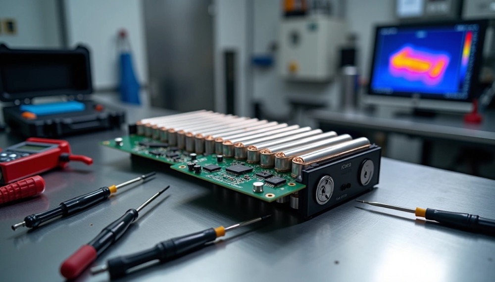
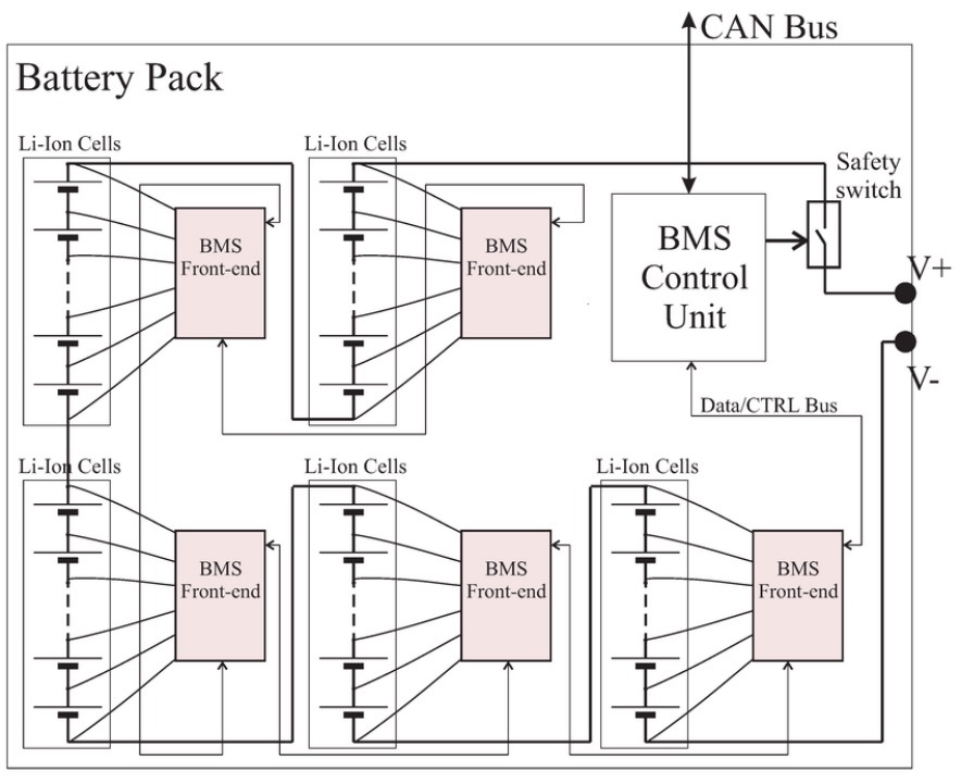 Image Source: Holo Battery
Battery pack design consists of three fundamental building blocks that determine electrical performance, operational reliability, and safety characteristics. Since 1965, battery manufacturers have developed these components to meet specific voltage, capacity, and environmental requirements across diverse applications.
Cell Types: Cylindrical, Prismatic, Pouch
Cell selection forms the foundation of custom lithium ion battery pack development. Each cell format exhibits distinct performance characteristics and manufacturing considerations:
Cylindrical cells utilize spirally wound electrodes and separators enclosed in steel or aluminum cans. The cylindrical geometry provides uniform mechanical stress distribution and efficient heat dissipation through radial cooling paths. Standard sizes include 18650 (18mm diameter, 65mm height), 21700, and 4680 formats with capacities ranging from 1.5Ah to 50Ah. The sealed metal housing offers superior mechanical protection against external impacts and internal pressure buildup.
Prismatic cells feature rectangular electrode stacks housed in welded aluminum or steel casings. These cells emerged in the early 1990s to maximize volumetric efficiency with typical dimensions of 100 x 200 x 10mm and capacities between 10-30Ah. The flat form factor achieves higher space utilization compared to cylindrical cells, however power density remains lower due to limited cooling surface area. Electric vehicle applications increasingly utilize prismatic cells where space constraints drive design decisions.
Pouch cells employ flexible metallized laminate pouches containing electrode stacks without rigid casings. This construction achieves 90-95% packaging efficiency but requires mechanical support structures and accommodation for 8-10% swelling after 500 charge cycles. The flexible format enables custom shapes for wearable devices and space-constrained applications.
Series and Parallel Cell Configurations
Cell arrangement directly determines pack voltage, capacity, and current delivery capability in custom battery designs. Battery pack configurations employ two basic connection methods:
Series connections multiply voltage while capacity remains constant. Connecting the negative terminal of one cell to the positive terminal of the next cell adds voltages together. Four 3.6V lithium-ion cells connected in series produce 14.4V nominal output.
Parallel connections increase capacity while voltage stays unchanged. All positive terminals connect together and all negative terminals connect together, multiplying amp-hour ratings by the number of parallel cells.
Most battery packs combine series and parallel arrangements to achieve target specifications. Industry notation describes configurations as “XsYp” where X represents cells in series and Y indicates parallel groups. Laptop batteries commonly use 4s2p configurations to deliver 14.4V with doubled capacity.
Battery management systems monitor and control pack operation to ensure safe performance within design parameters. A properly designed BMS performs multiple critical functions:
Cell monitoring tracks individual voltages, temperatures, and current flow to detect imbalances or fault conditions before they become dangerous.
Protection circuits prevent overcharge, over-discharge, and overcurrent conditions that can damage cells or create safety hazards.
Cell balancing equalizes charge levels across all cells to maximize pack capacity and prevent premature aging of weaker cells.
State estimation calculates remaining capacity (SOC) and overall health (SOH) to inform users and connected systems.
BMS complexity varies based on application requirements. Consumer electronics typically require basic protection functions, while electric vehicle systems incorporate hundreds of sensor inputs and sophisticated control algorithms. Medical and aerospace applications demand the highest reliability standards with redundant monitoring and fail-safe operation modes.
The BMS serves as the central intelligence system that transforms individual cells into a safe, reliable power source suitable for demanding applications.
Performance Optimization and Technical Trade-offs
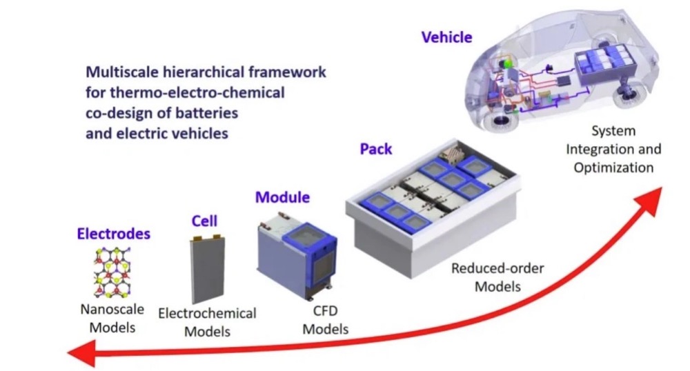 Image Source: EV Engineering & Infrastructure
Battery pack performance optimization requires evaluating competing design parameters to meet specific application requirements. The challenge lies in understanding how each design decision affects overall system performance and cost.
Energy Density vs Power Delivery Characteristics
Battery design fundamentally involves choosing between energy storage capacity and power delivery capability. Energy density (Wh/kg or Wh/L) defines the total energy stored per unit mass or volume, while power density (W/kg or W/L) determines the maximum current delivery rate.
These parameters operate inversely—optimizing for one typically reduces the other. Design priorities must align with application requirements:
- Energy-optimized designsutilize thicker electrodes with lower porosity and larger particle sizes to maximize energy storage capacity
- Power-optimized designsemploy thinner electrodes with higher porosity and smaller particle sizes to minimize internal resistance and enable rapid discharge
Custom lithium ion battery packs require electrode-level modifications to achieve target performance. Energy-dense batteries minimize conductive additives to maximize active material content, whereas high-power variants incorporate additional carbon black or graphite to reduce impedance.
Thermal Management System Selection
Operating temperature directly affects both performance and safety. Lithium-ion cells function safely between -20°C and 60°C, with charging limited to 0°C to 45°C to prevent lithium plating. Temperature management systems fall into two categories:
Passive cooling systems rely on natural heat transfer without external power consumption:
- Heat sink assemblies with enhanced surface area
- Heat pipes containing phase-change working fluids
- Phase change materials that absorb thermal energy during state transitions
Active cooling systems provide precise temperature control at the expense of additional power consumption:
- Forced convection systems for moderate thermal loads
- Liquid cooling plates for high-power applications requiring precise temperature control
- Immersion cooling for extreme thermal management requirements
Thermal simulation modeling allows identification of temperature gradients and hotspots during the design phase, enabling optimization of cooling system placement and capacity before prototype development.
Charge Control Strategies for Cycle Life Extension
Charging parameters significantly influence battery service life. Standard lithium-ion cells charge to 4.20V per cell, typically achieving 300-500 cycles before reaching 80% of initial capacity. Charge voltage reduction extends cycle life substantially—limiting charge voltage to 4.10V per cell increases cycle life to 600-1,000 cycles, while 4.0V per cell operation can achieve 1,200-2,000 cycles.
State of charge management provides additional cycle life benefits. Operating batteries within a 20-80% charge range significantly extends service life compared to full 0-100% cycling. Applications requiring maximum longevity benefit from charge-limiting circuits within the battery management system that prevent voltage excursions beyond predetermined safe operating limits.
Battery Safety Systems and Protection Circuits
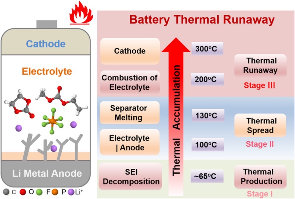 Image Source: ResearchGate
Lithium-ion chemistries require comprehensive safety systems due to their potential for thermal runaway, gas venting, and fire hazards under fault conditions. Safety protection from overheating is a critical component of every lithium battery pack. Our technical experience demonstrates that implementing robust protection circuitry directly affects both product liability and market acceptance.
Protection Circuit Modules for Voltage Control
The protection circuits are contained in what is commonly referred to as the protection circuit module (PCM). Overcharge protection activates when individual cell voltage exceeds 4.30V during charging, preventing electrolyte decomposition and crystal structure damage that can lead to toxic gas emissions or thermal events. Under-voltage protection engages when cell voltage drops below 2.20-2.50V per cell, preventing irreversible capacity loss and potential cell chemistry degradation that renders batteries unrechargeable.
Battery protection circuits for demanding applications utilize integrated circuits (ICs) with MOSFETs to switch lithium cells in and out of circuit based on monitored parameters. The over-current protection activates when the IC detects the upper current limit being reached and interrupts the circuit to prevent damage.
Lithium batteries operate safely between -20°C and 60°C, with optimal charging occurring between 0°C and 45°C. Temperature monitoring represents the most effective method for preventing thermal runaway propagation in custom battery pack designs. Critical prevention mechanisms include:
- Real-time temperature monitoring at individual cell level • Automatic isolation of problematic cells within milliseconds
• Built-in thermal suppression systems for high-energy applications • Emergency disconnect capabilities for fault conditions
The 2025 safety standards mandate that all lithium battery designs incorporate redundant thermal management pathways and demonstrate safe operation even when primary cooling systems fail.
Multi-Layer Safety Architecture
Primary safety circuits manage basic protection functions including over-voltage, under-voltage, over-current, and temperature monitoring. Secondary safety circuits provide backup protection when primary systems fail. High-reliability applications require multiple current protection thresholds with different response times. Premium battery management systems implement fail-safe designs where protection switches default to safe states upon control signal loss.
Our design methodology incorporates continuous monitoring of all safety systems with fault detection capable of transitioning to protected states within milliseconds. This approach ensures that secondary protection remains operational even if primary safety systems experience failures that could otherwise lead to hazardous thermal conditions.
Environmental and Mechanical Design Considerations
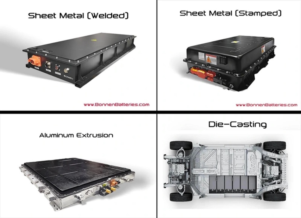 Image Source: Bonnen Battery
Environmental conditions determine battery pack longevity in operational applications. Mechanical design considerations frequently override electrical specifications when batteries encounter temperature extremes, vibration, moisture, or corrosive atmospheres during actual service conditions.
Harsh Environment Applications
Extreme operating environments subject battery packs to multiple stress factors simultaneously. Deep-space and underwater applications expose lithium-ion cells to radiation fields, pressure differentials, and temperature cycling that can degrade electrochemical performance. Environmental factors including corrosive gases, salt spray, and UV radiation require specialized housing materials and protective coatings.
Hazardous location applications demand explosion-proof enclosure designs with controlled venting systems. Valve-regulated cells prevent internal gas accumulation while maintaining hermetic seals required for hazardous area certification. Potting compounds provide additional protection through chemical-resistant, moisture-proof barriers that isolate sensitive circuitry from environmental contaminants.
Mechanical shock and vibration directly affect battery performance through electrode material displacement and internal connection fatigue. Extended vibration exposure causes active material spalling, reducing available capacity, while impact forces can displace internal components and create short-circuit conditions. Effective shock absorption requires specialized cushioning materials designed for battery pack applications.
Vibration isolation materials include:
- Silicone foams with controlled compression characteristics
- Rogers Poron® urethane foam for high-frequency dampening
- Bisco® silicone foam for temperature stability
- High-bond structural adhesives for component securement
Silicone materials maintain elastic properties across temperature ranges from -80°C to 250°C, providing consistent vibration isolation under varying thermal conditions. Proper component restraint prevents internal movement during transportation and operational vibration exposure.
Ingress Protection Standards and Sealing Methods
The IP rating system specifies environmental protection levels through two numerical designations—solid particle ingress (IP1x through IP6x) and liquid ingress protection (IPx1 through IPx8). Industrial applications typically require IP67 certification, ensuring complete dust protection and submersion resistance to 1 meter depth for 30 minutes.
Sealing methodologies include formed-in-place gaskets (FIPG) applied during assembly and cured-in-place gaskets (CIPG) that cure prior to installation. FIPG systems create permanent seals but prevent future disassembly, while CIPG gaskets allow component separation for service access. Gasket bead uniformity remains critical—dimensional variations or voids compromise environmental sealing effectiveness and potentially affect safety performance.
Regulatory Compliance and Certification Requirements
 Image Source: Large Battery
Regulatory compliance represents a mandatory aspect of custom battery pack commercialization. Our certification experience demonstrates that proper planning during the design phase significantly reduces both timeline and cost impacts.
Certification Testing and Documentation Requirements
Battery certification requirements depend on chemistry type and intended application. UN38.3 testing establishes the foundation for lithium battery transportation, encompassing eight specific tests: altitude simulation, thermal cycling, vibration, shock, external short circuit, impact, overcharge, and forced discharge. The testing process requires 17 sample packs and typically completes within 6-8 weeks. Consumer electronics applications require UL 2054/62133 certification, demanding 55 sample packs with testing cycles extending 12-14 weeks.
Certification costs vary significantly based on testing requirements:
- 3: USD 5,000-15,000
- UL 2054/62133: USD 10,000-25,000
- IEC 62133: USD 8,000-20,000
Manufacturers must complete certification before production scaling. Changing production facilities requires recertification regardless of design similarity, as certification reports specify manufacturer details and production location.
Battery Identification and Traceability Systems
European Union regulations mandate unique battery passport systems for EV and industrial batteries exceeding 2kWh capacity, effective January 2026. These digital passports require QR code accessibility and real-time data updates. South Korea implements similar battery identification requirements within battery management systems starting February 2025.
Required battery passport data includes:
- Manufacturing specifications, chemical composition, and application details
- Performance metrics and durability testing results updated throughout operational lifecycle
- Carbon footprint documentation (mandatory from July 2024)
- Recycled material content percentages for critical raw materials
The Global Battery Alliance Battery Passport initiative establishes standardized reporting frameworks for battery sustainability data worldwide.
Documentation Standards for International Markets
Shipping documentation requirements follow strict regulatory protocols. Required documents include:
- Shipper’s Declaration for Dangerous Goods specifying UN classification and shipping designation
- Material Safety Data Sheet detailing chemical composition and handling requirements
- Commercial invoice including HS classification code for customs processing
- Test certification reports demonstrating compliance with applicable safety standards
EPA battery labeling guidelines currently under development (expected finalization 2026) will standardize consumer information across battery categories to improve recycling compliance rates. These guidelines address product identification and end-of-life disposal procedures for battery-containing devices.
Custom battery pack design requires systematic integration of electrochemical, thermal, mechanical, and safety engineering principles. Cell selection, protection circuits, thermal management, and compliance testing all contribute to the final product’s operational reliability and commercial success.
The fundamental design challenge involves managing competing technical requirements. High energy density applications benefit from specific electrode configurations and charging parameters, while high power applications require different optimization strategies. Thermal management systems must address both normal operation and fault conditions, with lithium-ion chemistry requiring particular attention to prevent thermal runaway scenarios.
Safety protection represents a non-negotiable requirement for lithium battery systems. Primary protection circuits monitor voltage, current, and temperature parameters, while secondary protection systems provide backup functionality. The protection circuits are contained in what is commonly referred to as the protection circuit module (PCM), which manages the electronics of a rechargeable battery pack by monitoring its state, reporting that data, and controlling its environment.
Environmental considerations significantly impact design complexity and cost. The IP rating goes hand in hand with the battery enclosure development, determining how watertight, dust resistant, and dirt resistant the battery enclosure will be. Applications requiring higher IP ratings will increase costs and weight, so the protection level should match the actual operating environment requirements.
Certification requirements vary by application and geographic market. UN 38.3 testing is mandatory for lithium battery transportation, while UL 2054 and IEC 62133 apply to specific product categories. All of the costs and lead times of these tests will vary depending on the battery construction, capacity, pack size, and cycle requirements.
Battery technology continues advancing rapidly, with new regulations for battery identification and lifecycle tracking taking effect globally. Our technical staff will work with you to generate material specifications, product renderings, complete documentation, and prototypes that meet both current requirements and anticipated future standards.
The objective for any design is to keep the costs down and the timeline tight, and our experience has demonstrated that the only way to do that is to get an agreed upon specification developed prior to starting development.
For your next custom battery project, please contact Large Power!
Key Takeaways
Understanding the hidden complexities of custom battery design enables engineers to create safer, more efficient power solutions that meet specific application requirements while ensuring regulatory compliance.
- Cell selection drives performance: Choose cylindrical cells for durability, prismatic for space efficiency, or pouch cells for flexible form factors based on your application’s thermal and mechanical requirements.
- Safety systems prevent catastrophic failures: Implement multilayered protection against overcharge, over-discharge, and thermal runaway through redundant BMS circuits and active thermal management.
- Performance optimization requires strategic trade-offs: Balance energy density versus power delivery by adjusting electrode thickness, porosity, and charge voltage limits to maximize either capacity or discharge rates.
- Environmental design determines real-world longevity: Protect against vibration, shock, and moisture through proper cushioning materials, IP67-rated sealing, and specialized housing for harsh conditions.
- Regulatory compliance is mandatory for market entry: Secure UN38.3, UL 2054, and regional certifications early in development, with costs ranging $5,000-25,000 and timelines of 6-14 weeks.
The key to successful custom battery development lies in understanding that every design decision creates cascading effects across performance, safety, and compliance—making expert guidance essential for navigating these complex interdependencies.
FAQs
Q1. What is the optimal charging range for lithium-ion batteries? For maximum longevity, it’s recommended to keep lithium-ion batteries charged between 20% and 80% of their full capacity. This practice, known as the 20-80 rule, can significantly extend battery life compared to regularly charging to 100% or depleting to 0%.
Q2. How do different cell types affect battery pack design? Cell type selection impacts performance and design. Cylindrical cells offer durability and good thermal management, prismatic cells maximize space efficiency, and pouch cells provide flexibility for custom shapes. The choice depends on the specific application requirements.
Q3. What safety features are crucial in custom battery pack design? Critical safety features include overcharge and over-discharge protection, thermal runaway prevention systems, and redundant safety circuits. These mechanisms help prevent catastrophic failures and ensure safe operation across various conditions.
Q4. How does environmental protection factor into battery design? Environmental protection is crucial for battery longevity. This includes designing for vibration and shock resistance using specialized cushioning materials, and implementing proper sealing techniques to achieve appropriate Ingress Protection (IP) ratings for dust and water resistance.
Q5. What certifications are required for custom battery packs? Key certifications include UN38.3 for transportation safety, and UL 2054/62133 for consumer electronics. These certifications involve extensive testing of multiple sample packs and can take several weeks to months to complete, with costs ranging from $5,000 to $25,000 depending on the specific standards required.
 The type of
  Image Source:
 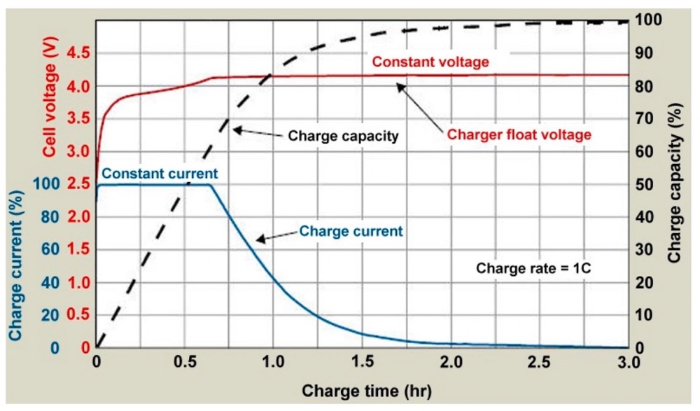 Image Source:
  Image Source: tritek battery
 Image Source:
  A fully charged lithium battery requires 14.6 volts, yet standard charging systems consistently fail to reach this critical threshold. The selection of appropriate
 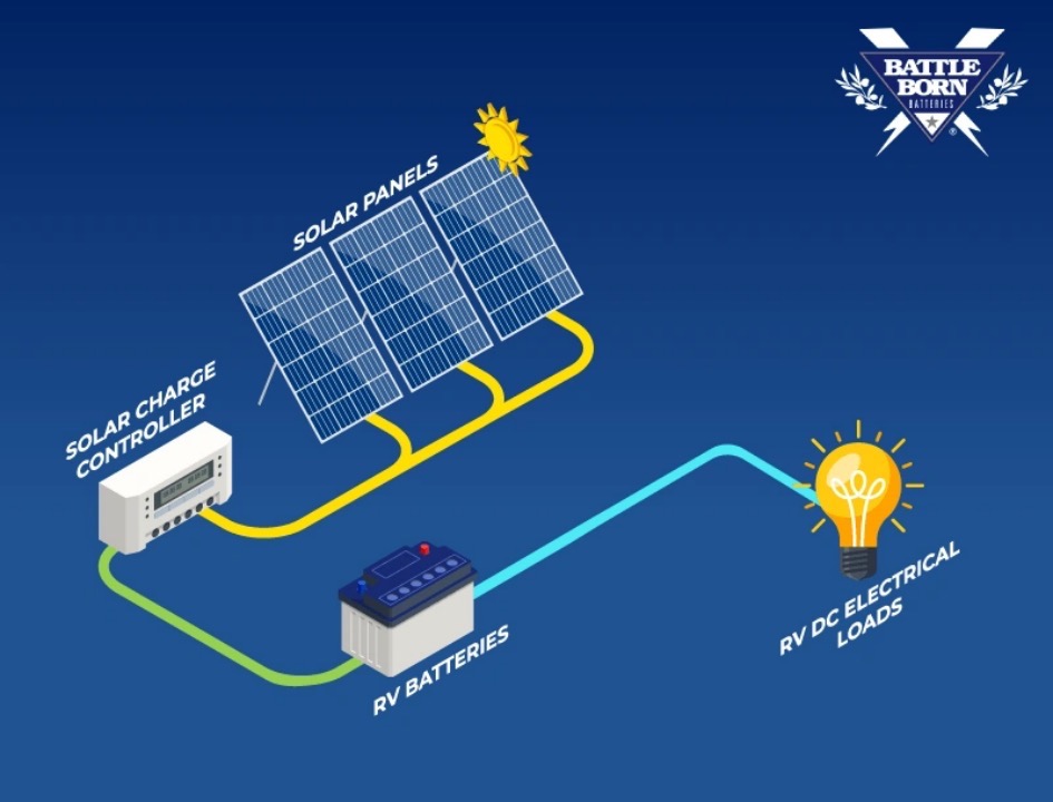 Image Source: Battle Born Batteries
 Image Source:
 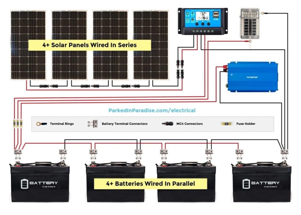 Image Source:
 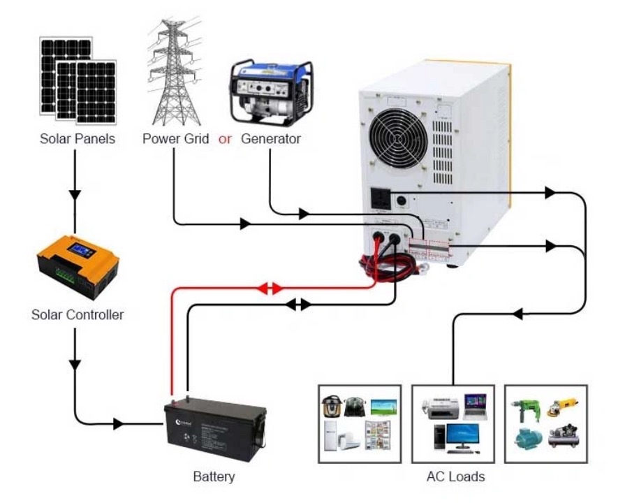 Image Source: Xindun Power
 Image Source:
  Heavy equipment batteries
 Image Source:
  Image Source:

