
The Tesla Model S lithium-ion battery system contains over 7,000 individual 18650 cells arranged in a sophisticated thermal management configuration. Custom 18650 battery pack designs for smaller applications follow similar engineering principles while offering significant advantages for specific power requirements.
Each 18650 lithium-ion cell delivers more than 13 watt-hours of energy density compared to 3.9 watt-hours from a typical AA battery. This energy density advantage makes 18650 cells the preferred choice for applications ranging from electric vehicle systems to portable electronics. The cylindrical form factor provides excellent thermal characteristics and standardized manufacturing benefits, though mechanical protection against vibration and puncture damage requires careful consideration.
Battery pack voltage is determined by series cell configuration. A 48-volt battery pack requires 13 cells connected in series when using 3.7-volt nominal cells. Capacity increases through parallel connections, with configurations like 13s4p (52 total cells) providing both voltage and current requirements for demanding applications.
Custom battery pack development involves multiple engineering disciplines: cell selection based on discharge characteristics, thermal management systems, protection circuitry, and mechanical enclosure design. The type of battery required is determined by the requirements of the device being powered: device voltage, load-current, and recharge time requirements; environmental considerations; physical space available; weight constraints; and regulatory and transportation requirements.
This technical guide covers the complete development process from specification through assembly, focusing on the engineering decisions and safety protocols essential for reliable custom lithium-ion battery pack construction.
Battery Pack Specification Development
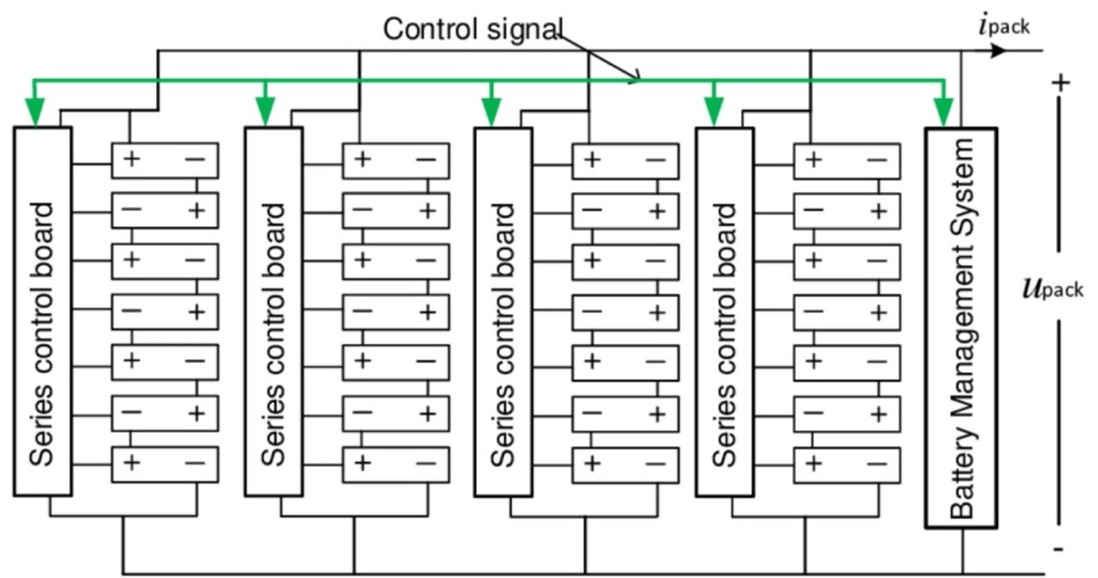
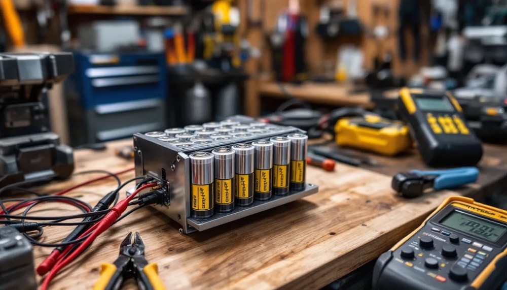
Image Source: Large Battery
Successful custom 18650 battery pack development begins with establishing comprehensive technical specifications. The first step is to work with the customer to help them finalize what their operating parameters and specifications are, which in turn will help us develop a scope of work for the entire project.
Electrical Parameter Determination
Lithium battery pack design requires two fundamental electrical specifications: voltage and capacity. A standard 18650 cell provides 3.6V or 3.7V nominal voltage, reaching 4.2V when fully charged. Series connections multiply this voltage – approximately 10 cells in series for a 36V system.
Cell capacity is rated in amp-hours or milliamp hours. The symbol for capacity is C or It, current X time. Parallel connections increase capacity proportionally. For example, if your application draws 50 watts for 4 hours, you require 200 watt-hours of capacity (50W × 4h = 200Wh).
The calculation process follows these steps:
- Determine individual cell capacity (typically 1800-3500mAh for quality 18650s)
- Calculate parallel configuration requirements based on total capacity needs
- Example: 2900mAh cells in a three-parallel configuration provide 8.7Ah total capacity
This methodology produces configuration notation such as “10S3P” – indicating 10 cells in series and 3 in parallel for a 36V 8.7Ah battery.
Application Requirements Analysis
The type of battery required is determined by the requirements of the device being powered: device voltage, load-current, and recharge time requirements; environmental considerations; physical space available; weight constraints; and regulatory and transportation requirements.
Critical application factors include:
Load Characteristics
- Continuous current draw versus peak current requirements
- Discharge rate specifications for high-performance applications
- Power cycle frequency and duration patterns
Physical Constraints
- Available space envelope and mounting provisions
- Weight limitations and structural requirements
- Thermal management considerations
Environmental ConditionsTemperature, humidity, and vibration exposure significantly impact cell selection. High-temperature applications benefit from prismatic cells with superior thermal management. Cylindrical 18650 cells provide the best robustness among lithium cell formats for mechanically demanding applications.
Chemistry selection involves trade-offs between performance characteristics. Standard lithium-ion cells deliver excellent energy density and availability. LiFePO4 cells offer superior safety and cycle life performance, though with increased weight and cost.
Technical Specification Documentation
A detailed specification sheet serves as the foundation for all subsequent design decisions. This document should include:
Primary Electrical Requirements
- Nominal voltage and full charge voltage limits
- Rated capacity at specified discharge rate
- Maximum continuous and peak discharge currents
- Expected cycle life performance
Mechanical and Environmental Specifications
- Physical dimensions and weight constraints
- Operating and storage temperature ranges
- Vibration, shock, and environmental protection requirements
- Mounting and connector specifications
Safety and Regulatory Parameters
- Protection circuit requirements and functionality
- Thermal management specifications
- Required certifications and compliance standards
The objective for any design is to keep the costs down and the timeline tight, and our experience has demonstrated that the only way to do that is to get an agreed upon specification developed prior to starting development. A comprehensive specification prevents scope changes during development that can extend timelines and increase costs significantly.
Battery Pack Configuration and Component Selection
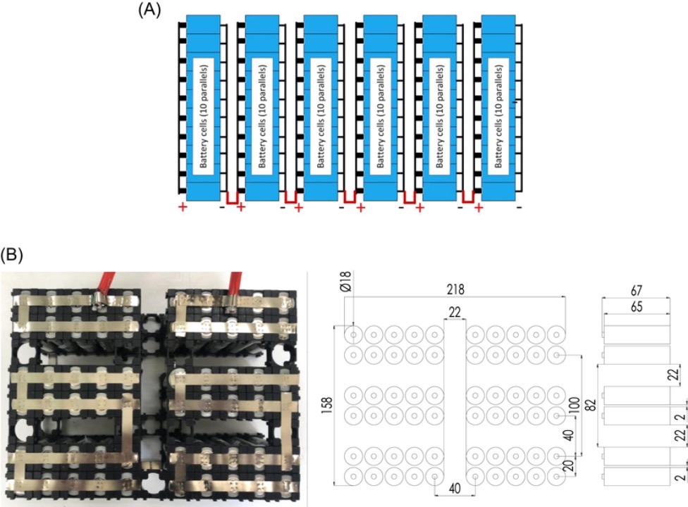
Image Source: ResearchGate
Cell configuration and component selection determine the fundamental performance characteristics of your custom 18650 battery pack. Systematic approach to these decisions prevents design errors and ensures the battery pack meets application requirements within specified operating parameters.
Series and Parallel Configuration Design
Battery pack voltage is achieved through series connections, where individual cell voltages combine arithmetically. Connecting four 3.7V cells in series produces 14.8V nominal voltage with unchanged capacity characteristics. Parallel connections maintain nominal voltage while increasing capacity proportionally to the number of cells connected.
Configuration notation follows industry standard “XsYp” format, indicating X cells in series and Y cells in parallel. A 4s2p configuration contains 8 total cells arranged to provide four times the individual cell voltage with twice the capacity.
Cell matching becomes critical in series configurations. The weakest cell determines overall pack performance and cycle life. High-voltage applications such as electric bicycle systems (36V-48V) require cells matched within 0.05V for optimal performance and safety.
18650 Cell Selection Criteria
Cell selection requires evaluation of multiple performance parameters against application requirements. Established manufacturers including LG Chem, Molicel, Samsung, Sony|Murata, and Panasonic|Sanyo provide consistently rated products with verified specifications.
Current market limitations define realistic performance boundaries. No legitimate 18650 battery exceeds 3600mAh capacity or 30A continuous discharge rating (CDR). Cells advertising higher specifications typically involve fraudulent rating practices.
Performance trade-offs require careful consideration:
- High capacity cells (3000-3500mAh) typically limit continuous discharge to 10A or less
- High current cells (20-30A CDR) usually provide 2000-2500mAh capacity
- Balanced performance cells like Samsung 25R, LG HG2, and Samsung 30Q offer moderate capacity with 15-20A discharge capability
Temperature characteristics vary significantly between cell types. High-discharge cells generate more internal heat during operation, requiring thermal management considerations in pack design.
Physical Layout and Thermal Considerations
Cell arrangement affects electrical performance, thermal behavior, and mechanical stability. Cylindrical 18650 cells provide superior surface-to-volume ratio compared to prismatic formats, facilitating heat dissipation through natural convection pathways between cells.
Strategic cell spacing prevents thermal runaway propagation while maintaining compact pack dimensions. High-current applications require minimum 2-3mm spacing between cells to ensure adequate airflow for cooling.
Mechanical considerations include vibration resistance, especially for mobile applications. Cell holders or mechanical restraints prevent movement that could damage interconnections or cause internal cell damage.
Battery Management System Selection
Battery management systems provide essential protection functions for lithium-ion battery packs. While lithium-ion batteries can operate without BMS protection, this approach creates significant safety hazards including fire and explosion risks.
BMS selection criteria include:
- Maximum continuous current rating with 15% safety margin above application requirements
- Balancing capability for all cells in series configuration
- Protection thresholds compatible with selected cell specifications
- Communication interfaces if system monitoring is required
Advanced features such as Bluetooth connectivity enable remote monitoring of battery status, cell voltages, and temperature conditions. Temperature monitoring becomes essential for applications operating in variable environmental conditions.
Current requirements determine appropriate BMS sizing. Small applications such as USB power banks typically require 10-20A capacity, while larger systems including power walls and electric vehicle applications demand 50A+ current handling capability.
Protection circuit parameters must match cell specifications exactly. Over-voltage protection typically activates at 4.2-4.3V per cell, while under-voltage protection engages at 2.5-3.0V per cell depending on chemistry and manufacturer recommendations.
Required Equipment and Materials
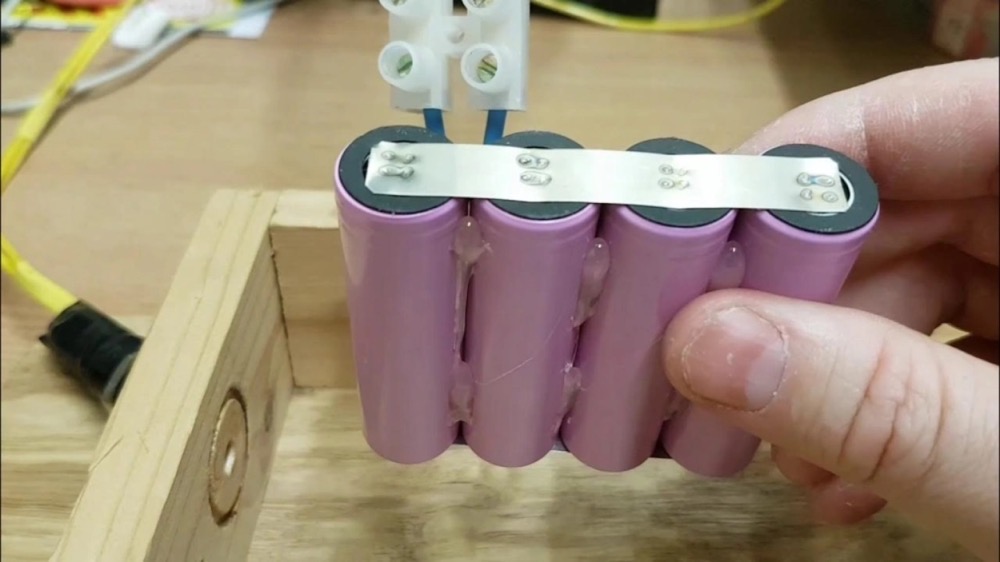
Image Source: Nuranu
Professional battery pack assembly requires specific equipment and materials to ensure both electrical integrity and safety compliance. The quality of tools and materials directly impacts the reliability and performance characteristics of the finished battery pack.
Critical Assembly Equipment
Spot welder specifications determine connection quality and cell integrity. Professional spot welders deliver controlled energy pulses, typically 1-3 kilojoules, to create metallurgical bonds between nickel strips and cell terminals without thermal damage. Soldering iron connections to lithium cells are not recommended due to excessive heat exposure that can damage internal cell components.
Multimeter accuracy affects voltage measurement precision and connection verification. Digital multimeters with 0.1V resolution provide adequate precision for cell voltage matching and pack testing. This instrumentation enables verification of individual cell voltages prior to assembly and diagnosis of electrical continuity throughout the pack.
Additional required equipment includes: • Heat gun capable of 300-500°C for heat shrink application • Wire stripping tools rated for 12-16 AWG conductors • Soldering iron minimum 80W capacity for auxiliary connections
Connection Materials and Insulation
Nickel strip specifications must match current-carrying requirements. Pure nickel strips 0.1-0.15mm thickness provide optimal balance between flexibility and current capacity for typical 18650 applications. Current capacity varies with strip width: 5mm strips handle approximately 10A continuous current, while 8mm strips support 15A continuous operation.
Cell holders provide mechanical stability and thermal management benefits. These components maintain consistent cell spacing, reduce mechanical stress from vibration, and facilitate air circulation for thermal regulation. Precision-molded holders ensure proper alignment during spot welding operations.
Essential insulation materials include: • Fish paper (vulcanized fiber) rated for electrical insulation applications • Kapton polyimide tape for high-temperature environments • PVC heat shrink tubing with 2:1 shrink ratio for pack encapsulation • Terminal insulator rings preventing accidental short circuits
Safety Equipment and Workspace Configuration
Personal protective equipment is mandatory for lithium battery assembly operations. Safety glasses prevent eye injury from welding sparks or electrolyte exposure. Insulated gloves protect against electrical shock and provide thermal protection during assembly procedures.
Workspace preparation eliminates conductive materials that could create unintentional electrical paths. Non-conductive work surface materials prevent accidental short circuits during cell handling and assembly. Statistical analysis indicates that most battery-related incidents occur during construction rather than operational use.
Ventilation requirements address fume exposure from soldering flux and heat shrink materials. Cell handling procedures prevent mechanical damage that compromises internal separator integrity. Organized storage in non-conductive containers reduces handling risks and maintains cell organization throughout the assembly process.
Proper preparation protocols significantly improve both safety outcomes and assembly quality for custom 18650 battery pack construction projects.
Custom Lithium-Ion Battery Pack Assembly
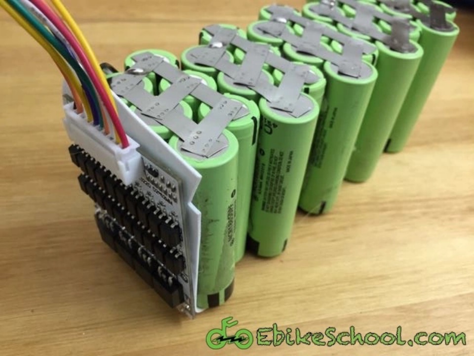
Image Source: EbikeSchool.com
The assembly phase requires systematic execution of established procedures to ensure both safety and performance parameters are met. Cell configuration, interconnection methodology, and protection circuit integration determine the final pack’s operational characteristics.
Cell Configuration and Mechanical Assembly
Arrange 18650 cells according to the predetermined series-parallel configuration. The first parallel group positions with positive terminals oriented upward, followed by the second group with negative terminals upward, alternating for subsequent groups. This configuration enables proper series connections between parallel groups while maintaining electrical isolation during assembly. Cell voltage matching within each parallel group is critical – voltage differentials exceeding 0.1V can create dangerous current imbalances during operation.
Cell holders provide multiple engineering benefits: thermal management through controlled spacing, mechanical stability under vibration, and electrical isolation between cell groups. For temporary assembly without holders, high-temperature adhesive materials rated above 80°C provide adequate cell retention.
Interconnection Methods and Procedures
Spot welding represents the optimal interconnection method for lithium-ion cell assembly. The process delivers precise thermal energy without compromising cell integrity or internal chemistry. Properly executed spot welds demonstrate mechanical strength exceeding that of the nickel conductor strip – failure should occur through strip material rather than weld separation.
Nickel strip preparation requires coverage of all parallel group terminals with 10mm extra for BMS connections extending beyond the cell contact area. Series interconnections utilize smaller strips bridging positive terminals of one group to negative terminals of the adjacent group. Strip thickness typically ranges from 0.15mm to 0.20mm depending on current requirements and thermal constraints.
Battery Management System Integration
BMS connection sequencing follows established safety protocols. Initial connection attaches the most negative balance lead (B-) to the pack’s negative terminal. Subsequent balance leads connect sequentially: B1 to the first series junction, B2 to the second junction, continuing through the complete series chain.
Pre-tinning both balance leads and connection points separately minimizes thermal exposure to cells during final assembly. Each connection requires mechanical verification through gentle tension testing to confirm adequate joint strength. Balance lead wire gauge must accommodate monitoring current requirements while maintaining flexibility for pack assembly.
Insulation and Environmental Protection
Electrical insulation prevents short circuits that can result in thermal runaway conditions. Fish paper insulation applies to all positive terminals and between cell groups to maintain electrical isolation. Kapton tape provides high-temperature insulation for exposed connections, particularly around nickel strips and BMS connection points.
Heat shrink tubing provides the final environmental barrier, offering protection against moisture, mechanical damage, and electrical short circuits. Applications requiring enhanced durability benefit from rigid enclosures designed to accommodate thermal expansion and provide impact protection. The overall enclosure design must maintain thermal management pathways while providing adequate mechanical protection for the intended application environment.
Battery Pack Testing and Validation Procedures
Comprehensive testing protocols are essential for custom 18650 battery pack validation before deployment. The testing phase reveals performance characteristics and identifies potential safety issues that require correction prior to operation.
Voltage Verification and Cell Balance Assessment
Multimeter verification of total pack voltage confirms proper series configuration alignment with design specifications. Pack voltage measurements should fall within the expected range based on individual cell voltages and series count. Individual cell voltages require simultaneous measurement to identify cell imbalances that indicate manufacturing inconsistencies or connection problems. Voltage imbalances exceeding 0.1V between cells in the same parallel group suggest potential safety hazards including thermal runaway conditions.
The measurement process involves testing each balance lead connection point sequentially. Record individual cell group voltages and calculate the difference between highest and lowest readings. Acceptable balance ranges depend on cell chemistry and age, with new lithium-ion cells typically maintaining balance within 0.05V.
Load Testing Protocol Implementation
Custom lithium battery pack performance validation requires controlled load testing under specified conditions. The standardized testing sequence follows established protocols:
- Condition the battery pack to ambient temperature (20°C ±2°C)
- Connect calibrated electronic load equipment rated for pack specifications
- Apply constant current load at C/5 discharge rate initially
- Monitor cell voltages, pack temperature, and current stability
- Document capacity measurements and compare against design targets
Load testing reveals actual capacity versus rated specifications and identifies cells with higher internal resistance. Voltage stability throughout the discharge curve indicates cell quality and connection integrity. Never discharge below 3.0V per cell during testing, as lithium cells suffer permanent capacity reduction from over-discharge.
Troubleshooting and Issue Resolution
Common failure modes in custom battery pack assemblies include charging system incompatibility, mechanical connection failures, and thermal management issues. Charging problems typically result from BMS parameter conflicts or charger voltage/current mismatches. Insufficient capacity measurements often indicate loose nickel strip connections or cell voltage imbalances. Temperature elevation during testing suggests inadequate thermal design or excessive internal resistance requiring immediate investigation.
Systematic troubleshooting involves isolating variables through individual component testing. Check BMS functionality independently, verify all mechanical connections under light load, and confirm proper thermal management through temperature monitoring during extended operation.
Summary
Custom 18650 battery pack construction requires systematic engineering approach, quality component selection, and adherence to established safety protocols. This development process spans multiple technical disciplines from electrochemical cell matching through thermal management system design and protection circuit integration.
Safety protection from overheating is a critical component of every lithium battery pack. The Battery Management System (BMS) provides essential protection functions: over-voltage protection, under-voltage protection, over-current protection, and thermal monitoring. These protection circuits are contained in what is commonly referred to as the protection circuit module (PCM), which manages the electronics of a rechargeable battery pack by monitoring its state, reporting that data, and protecting the battery.
Cell selection determines pack performance characteristics. Established manufacturers like Samsung, LG Chem, and Panasonic maintain rigorous quality standards essential for reliable operation. Cells perform differently due to the diverse processes used by various manufacturers, making quality cell selection fundamental to pack reliability.
The assembly process requires precision in spot welding techniques, proper insulation materials, and systematic connection procedures. Fish paper insulation prevents shorts between cell groups, while nickel strip thickness must match current requirements. Temperature considerations affect every aspect of pack design, from cell spacing for thermal management to protection circuit parameters.
Testing procedures verify electrical specifications and thermal performance before deployment. Load testing reveals how the battery pack performs under real-world conditions, while voltage monitoring identifies potential cell imbalances that could affect safety or performance.
Proper construction techniques result in battery packs that meet specified voltage, current, and capacity requirements while maintaining safety standards throughout their operational life. The engineering decisions made during design and assembly phases determine long-term reliability and performance of the finished power system.
For any custom battery pack inquiry, please consult with custom battery pack manufacturer, Large Power
Key Takeaways
Building a custom 18650 battery pack requires careful planning and safety-first approach to create reliable, cost-effective power solutions for your specific needs.
- Define requirements first: Calculate exact voltage (cells in series) and capacity (cells in parallel) needs before purchasing components to avoid costly mistakes.
- Use quality cells and BMS: Stick to reputable brands like Samsung, LG, or Panasonic, and never skip the Battery Management System for safety protection.
- Spot weld, don’t solder: Spot welding creates stronger connections without heat damage to cells, while proper insulation prevents dangerous short circuits.
- Test thoroughly before use: Verify voltage balance and perform load testing to ensure safe operation and identify potential issues early.
- Prioritize safety throughout: Wear protective gear, work in ventilated areas, and handle cells carefully to prevent accidents during assembly and operation.
When executed properly with attention to detail and safety protocols, custom 18650 battery packs deliver superior performance compared to off-the-shelf alternatives while providing valuable hands-on experience with battery technology.
FAQs
Q1. Is it safe to build a custom 18650 battery pack? Building a custom 18650 battery pack can be safe if proper precautions are taken. Always use quality cells from reputable manufacturers, include a Battery Management System (BMS) for protection, and follow proper insulation and assembly techniques. Wear safety gear and work in a well-ventilated area.
Q2. What tools do I need to build a custom battery pack? Essential tools include a spot welder, multimeter, heat gun, wire stripper/cutter, and soldering iron. A spot welder is crucial for safely connecting cells without heat damage. You’ll also need materials like nickel strips, cell holders, and insulation materials.
Q3. How do I determine the right configuration for my battery pack? Calculate your voltage needs (cells in series) and capacity requirements (cells in parallel) based on your application. For example, a 36V battery pack would require 10 cells in series using 3.7V cells. Consider factors like power draw, discharge rate, and physical constraints.
Q4. What’s the best way to connect 18650 cells in a battery pack? Spot welding is the preferred method for connecting 18650 cells. It creates stronger connections without heat damage to the cells. Use appropriately sized nickel strips and ensure proper insulation between cell groups. Avoid soldering directly to cells as it can cause internal damage.
Q5. How do I test my custom battery pack after assembly? After assembly, check the total pack voltage and individual cell voltages using a multimeter. Perform load testing to assess performance under real-world conditions. Monitor for any voltage drops or heating issues. Always test the BMS functionality before considering the project complete.


