

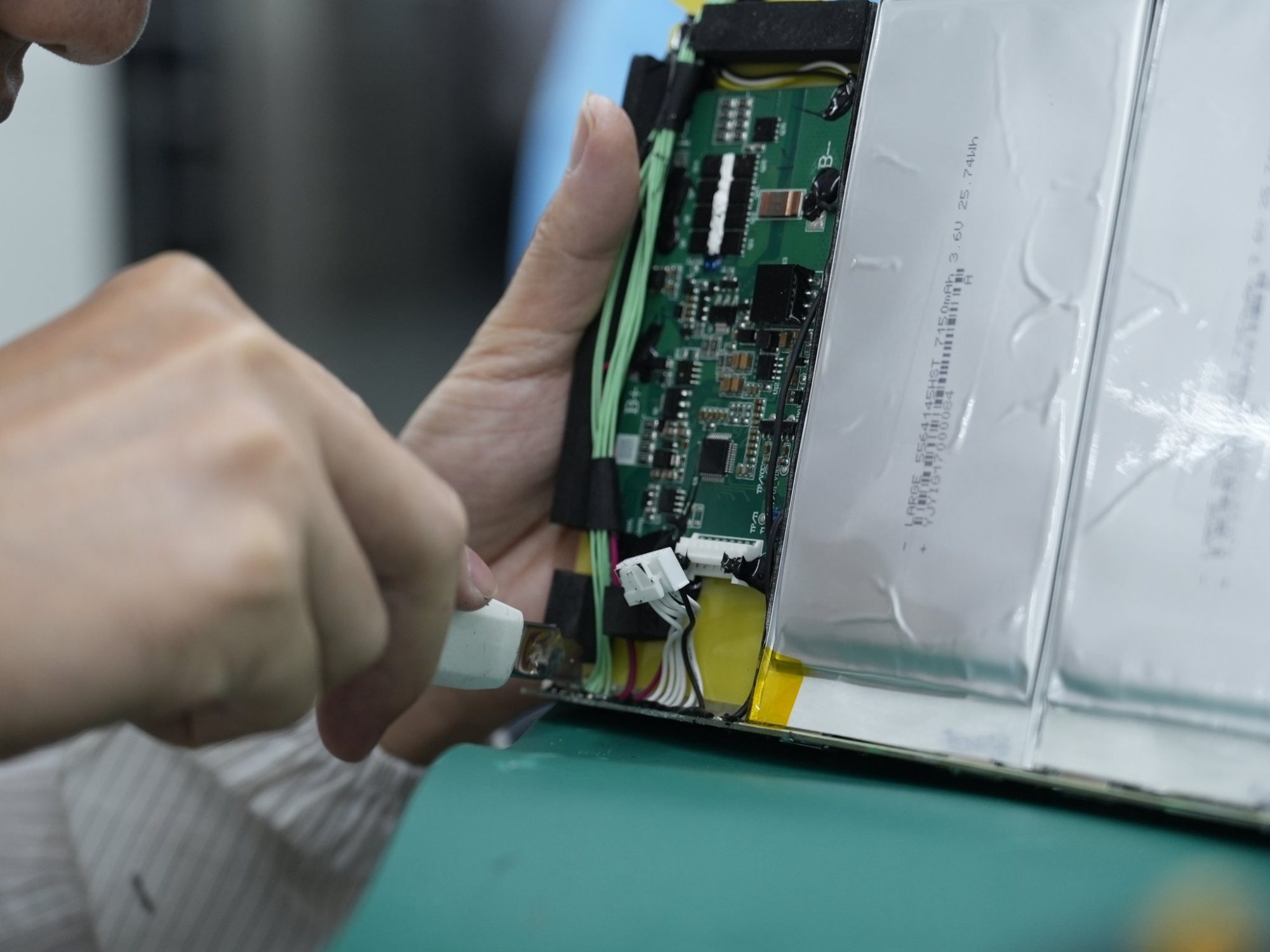
A 1S2P LiPo pack connects two compatible pouch cells in parallel to form one series group. Capacity can increase relative to one cell, but safe current sharing depends on cell matching, connection resistance, temperature and protection design. The arrangement does not automatically provide redundancy.
Part 1: Define the Cell and Pack Requirements
1.1 Specify more than nominal capacity
Use approved cell models with compatible charge voltage, operating limits and manufacturing controls. State the required finished dimensions, runtime, current waveform and charging conditions. Two cells with the same printed capacity may have different impedance, aging behavior or permissible current.
1.2 Distinguish parallel cells from complete packs
Parallel cells inside one engineered pack are not equivalent to connecting two protected battery packs at their outputs. Separate packs introduce additional switching and recovery behavior that requires its own system assessment.
Part 2: Understand Current Sharing
2.1 Resistance controls the split
The branches do not necessarily carry half the current each. Cell impedance, tabs, welds, wires, connector paths and their temperatures all influence the division. Assess both charging and discharging, including pulses.
Before initial parallel connection, unequal cell voltages can create equalization current. Define cell preparation and assembly controls with the cell manufacturer and qualified pack engineering team; do not directly connect mismatched loose cells as a field procedure.
2.2 Validate thermal and aging effects
A branch that carries more current may heat differently. Unequal cooling and aging can change the split over time. Measure branch behavior during development where practical, and verify the complete operating envelope rather than relying only on a room-temperature resistance screen.
Part 3: Design Protection and Interconnects
3.1 Recognize monitoring limitations
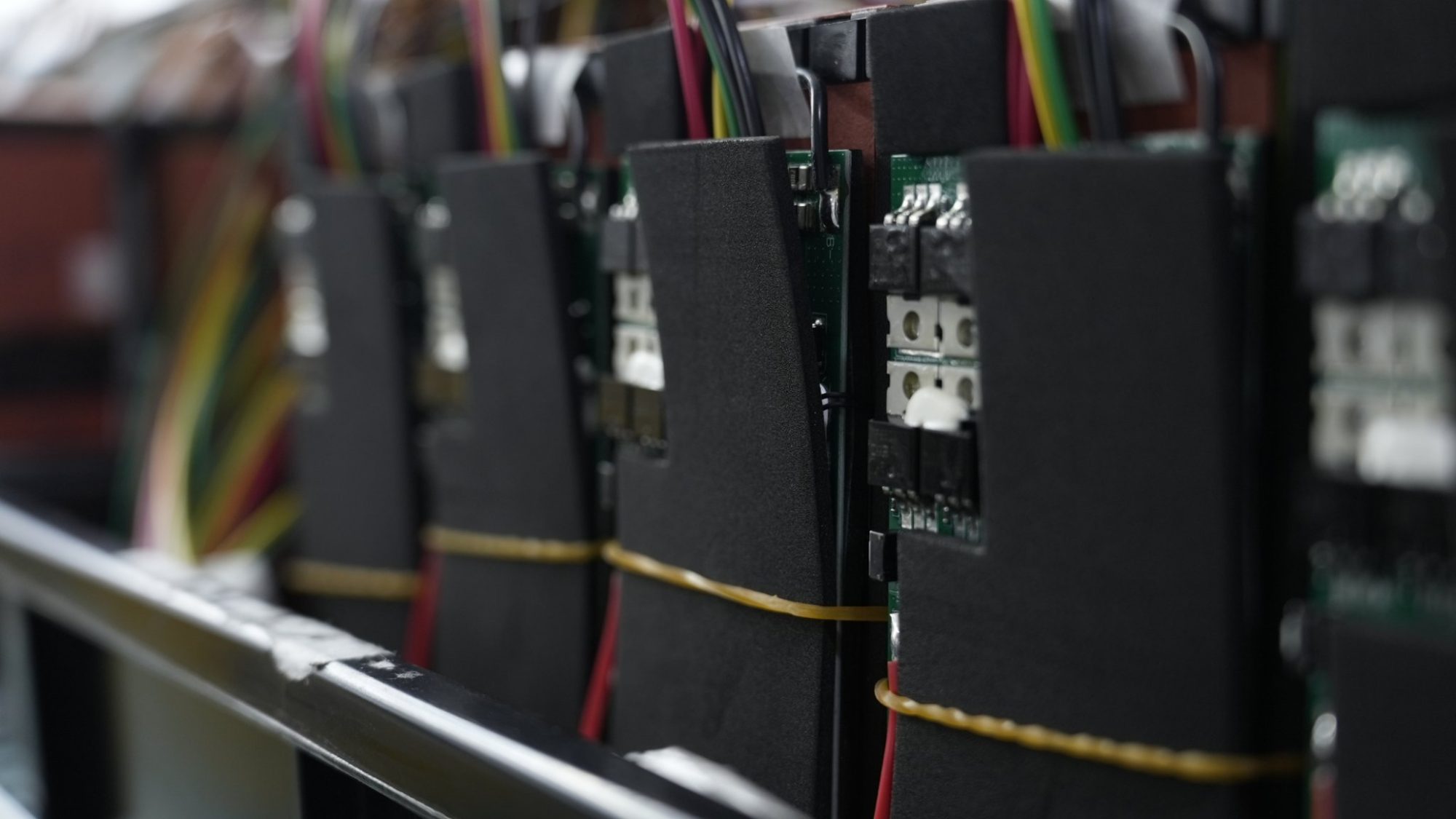
A protector measuring the single parallel-group voltage does not independently identify each cell’s condition. Total-current measurement may also conceal unequal branch currents. Sensor placement and fault analysis must address these limitations.
Define the actual PCM or BMS functions, including charge/discharge interruption, temperature protection and recovery. A PCM rating alone does not establish branch protection.
3.2 Analyze credible faults
Review a broken tab, poor weld, high-resistance connection, sensor failure and internal cell fault. If one branch becomes unavailable, the remaining branch may carry more than intended. Determine the appropriate containment and protective measures through design analysis and validation.
Part 4: Integrate the Finished Pouch Pack
4.1 Control mechanical loading
Allow for the approved cell thickness tolerance and lifecycle expansion. Keep hard edges, concentrated pressure and unsupported wiring away from the pouch and tabs. The mounting design must follow cell-specific guidance.
4.2 Match charging to the selected cells
The pack remains a single series group, but its permitted charge current is not automatically twice an arbitrary cell rating. Verify current sharing, temperature, charger termination and protection interactions in the assembled product.
Part 5: OEM Verification and Production Controls
Approved cell identity, lot records and matching criteria.
Branch-path resistance and assembly process controls.
Charge and discharge waveform and thermal measurements.
Fault-response and recovery evidence.
Finished dimensions and host-integration checks.
Controlled drawings, BOM and change notifications.
FAQ
Does 1S2P double the output voltage?
No. Parallel connection increases capacity, while the voltage remains that of one series group.
Can either cell fail without affecting operation?
Do not assume that. Fault behavior depends on the cell failure and protective architecture.
What information should an OEM provide?
Share the finished envelope, load profile and charging requirements through the custom battery project inquiry.


