

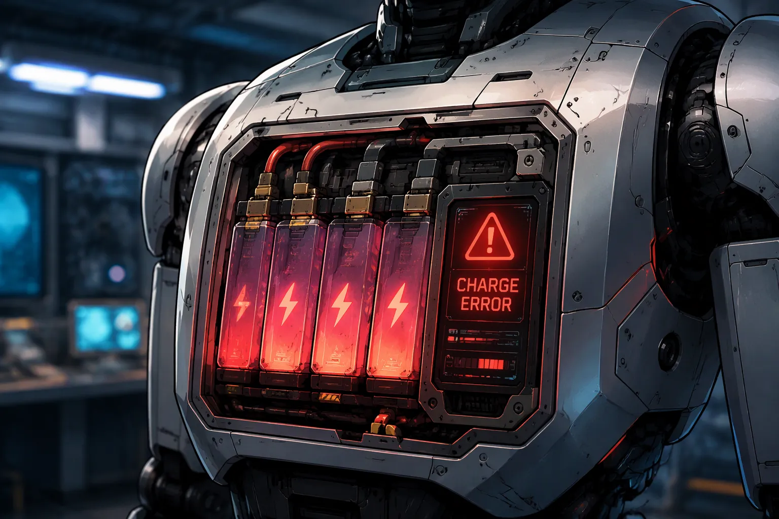
Quick Answer: When a robot battery pack limits regenerative charging because of high state of charge, low cell temperature, or a BMS charge-current limit, the host must reduce regeneration or manage the returned energy through another designed path. The OEM should verify DC bus voltage and the required braking response during a representative deceleration, including when the BMS reduces charge acceptance or disconnects the pack.
Explore robot battery solutions for pack integration and validation.
When a robot battery pack is full or can’t accept more charge, the regenerative current in robot battery packs has nowhere to go into the cells. The system has to route that energy to another load or dissipate it as heat. If not, the voltage rises and damage occurs. So regenerative current in robot battery packs is a normal energy-management problem for braking robots, not a rare case. A lithium-ion pack at 100% state of charge will not take current. Accelerazero explains what happens clearly:
As the battery gets close to 100% state-of-charge (SOC), the energy it can take in starts to drop, and at some point it can’t take any more (fully charged). If you keep pushing energy back into the battery after it hits 100% SOC, you can damage the battery and create a safety risk.
When the pack limits charge current, the OEM should verify how the host controls DC bus voltage and maintains the required braking response.
- Any time a battery can’t take the regenerative current the motor makes, several problems can happen. One is that the system voltage can spike and damage the parts on the system power bus, including the battery. It also affects the braking power.
- The battery in the vehicle must be able to absorb the regenerative current under all operating conditions. The battery or the system can add extra regen absorption components, like a bleeding resistor, to sink the extra regenerative current the pack can’t take. This requires careful monitoring of the regenerative current the motor produces and the regen current absorption capability the BMS calculates. Switches can control the flow of regenerative current and keep the braking and regeneration system working smoothly.
This article looks at how regenerative current in robot battery packs works, the risks of unmanaged excess energy, and practical solutions.
Key Takeaways
- Regenerative braking turns robot movement into electrical energy. The battery pack saves this energy to use later.
- A battery pack that is full or cold cannot take in more charge. The extra energy has to go to another load or be given off as heat.
- Regenerative energy that is not managed can harm battery cells and the electrical system. It can cause overvoltage and safety risks.
- Several methods handle extra energy: retarders, bigger batteries, telematics, brake choppers, and snubber networks. Each one fits different robot needs.
- Plan the system to handle regenerative current from the beginning. Work with the host controller and the battery management system together so everything runs safely.
Part 1: Regenerative Current in Robot Battery Packs
1.1 The Regenerative Braking Path
A braking robot motor works like a generator. The motor turns kinetic energy into electrical energy instead of losing it as heat. That energy flows back toward the lithium-ion pack. Engineers call this flow regenerative current in robot battery packs. The pack saves the energy for the next move. This recovery matters most in warehouse robots, medical carts, and inspection platforms that stop and start many times per shift.
The pack chemistry shapes how well this works. LiFePO4, NMC, LCO, and LMO cells all take charge, yet each has its own voltage and current behavior. The pack voltage must stay above the motor’s back-EMF for current to flow into the cells. A full pack sits at its top voltage. The voltage gap between the motor and the pack shrinks. Less current enters the cells, and the braking energy has fewer places to go.
1.2 Charge Limits and BMS/Host Coordination
A nearly full pack has little room for more charge. Sparrowcar explains that the battery management system lowers or turns off regen to prevent overcharging. Cold cells take charge less efficiently, so regen may be limited until the pack warms up. This is a protective feature, not a fault. It helps avoid lithium plating and other degradation modes.
The host controller and the BMS must share this limit during braking. The BMS checks charge current, cell temperature, and state of charge in real time. It then decides how much regen current to accept. Without a CAN interface, the BMS cannot tell the inverter how much charge power the pack can take. The inverter keeps pushing current, and overvoltage or damage can follow. A coordinated host/BMS design closes this gap. The BMS publishes its charge limit, and the host trims motor braking torque to match. For deeper coverage of BMS architecture, see battery management and protection.
Part 2: When Extra Energy Has Nowhere to Go
2.1 Pack-Level Risks
A full pack still gets current when the host keeps braking. The cells cannot store that charge. Cell voltage climbs above the upper cutoff, and the electrolyte starts to break down. Gas forms inside the can, pressure rises, and the safety vent may open. This failure chain makes overvoltage a safety event, not just a performance issue.
Aging speeds up at the same time. Each overvoltage event adds to the solid electrolyte interphase layer and uses up lithium inventory. Capacity fades faster than the datasheet predicts. The effect differs by chemistry. LCO cells (about 3.7 V nominal, 180–230 Wh/kg, 500–1,000 cycles) sit near their voltage ceiling at full charge and take little overshoot. NMC cells (3.6–3.7 V, 160–270 Wh/kg, 500–1,000 cycles) act in a similar way. LiFePO4 (3.2 V, 100–180 Wh/kg, 2,000–5,000 cycles) has a flatter curve and a wider margin, yet it still ages when pushed past its limit. LMO (3.7 V, 120–170 Wh/kg, 300–700 cycles) runs hotter under abuse. These are cell-level reference ranges, not pack guarantees. Pack limits depend on the BMS, the cooling design, and the cell matching.
2.2 System-Level Risks
The pack is only one part of the circuit. Regenerative current in robot battery packs also flows into the DC bus and its capacitors. Custom Robot Servo describes the mechanism: during rapid deceleration or vertical descents, permanent magnet synchronous motors act as generators and pump kinetic and gravitational energy back into the 24V–72V DC bus through the inverter bridge. If the charge path opens and no other sink is available, that current charges the bus capacitor. Custom Robot Servo gives an illustrative constant-current estimate:
dV/dt = I_net / C_bus 30 A / 0.001 F = 30,000 V/s = 30 V/ms
A rise from 50V to 80V would take 1 ms under those assumptions. This is a linear constant-current estimate, not an exponential rise or a measured failure waveform.
The consequences follow quickly. Drive overvoltage protection may interrupt controlled braking, which is dangerous on a ramp or in a lift axis. Excursions beyond component ratings can damage the power stage. Custom Robot Servo notes that the bus voltage can rise until it punches through the inverter MOSFETs’ drain-to-source breakdown voltage, trips the drive into overvoltage lockout, or triggers a battery BMS disconnect. A medical cart that stops mid-procedure, a security patrol robot that faults at a stair edge, or an AGV that drops a load in a warehouse all trace back to the same missing sink.
Part 3: Management Strategies Compared

3.1 Retarders, Capacity, and Telematics
An extra retarder is a separate braking device. It turns motion into heat before the energy reaches the pack. It fits robots with long downslopes or heavy payloads, like lift-assist carts in infrastructure settings. The drive train carries less stress, and the pack sees a smaller charge pulse. The trade-off is extra mass and a second wear item to service.
A bigger battery gives the pack more headroom to absorb returned energy. A larger NMC or LiFePO4 pack raises the ceiling before the charge limit arrives. This approach suits robots with plenty of space and a duty cycle that already needs longer runtime. Cost and weight rise with every added cell, so the gain must justify the volume.
Smart telematics adds sensing and communication. The system logs state of charge, temperature, and current. Then it predicts when the pack will reject charge. Fleet managers in security patrol or medical logistics can schedule routes around those windows. Telematics does not create a sink for excess energy. It buys time and visibility, and it pairs well with any other method.
3.2 Brake Choppers and Snubber Networks
A brake chopper is a fast electronic switch. It connects a resistor across the DC bus when voltage climbs too high. The resistor turns the surplus into heat, and the bus returns to a safe level. Ganservo describes the division of labor in a robot drive:
- Regenerative braking returns mechanical energy to an accepting electrical source, such as a battery or bidirectional supply. Resistor-based dynamic braking dissipates returned energy as heat. A robot may use both: recover energy while the battery accepts charge, then dissipate excess energy when it cannot.
- An independent hardware chopper can handle bus energy while motion control limits regeneration during normal operation. Fast switching overshoot also needs suitable layout, decoupling, and any required snubber or clamp: a brake resistor is not a substitute for those measures.
- Integrated chopper plus external DBR: Dissipate energy locally when the source cannot accept it. Minimum resistance, pulse current, duty, thermal mounting. Full protection-path waveform and resistor pulse qualification.
- Locate the chopper and its supply on the drive side of any contactor that removes the normal energy sink.
- Require pulse-overload curves, allowed initial temperature, repeated-pulse limits, resistor temperature protection, and chopper thermal data. An open resistor, disabled chopper, or lost control supply needs a defined fault response. ABB’s Electrical braking guide, sections 3.2 and 4 discusses chopper duty and thermal sizing in industrial drives; its mains-drive examples are not low-voltage product ratings.
A dissipative snubber network works on a smaller scale. It absorbs short voltage spikes and ringing at the switching devices. Regenerative current in robot battery packs that a full pack cannot absorb may be dissipated in such a network, yet the snubber handles transients rather than sustained braking energy. Designers often pair a chopper for bulk energy with a snubber for fast edges. This combination keeps the bus stable in industrial robots and transportation platforms alike.
Part 4: Choosing and Integrating a Strategy
4.1 Matching Solution to Duty Cycle and Chemistry
Begin with the duty cycle. A warehouse AMR that stops every few meters sends back small, frequent pulses. A lift axis or a downhill inspection platform sends back large, steady energy. Small pulses work well with a snubber plus tight host/BMS coordination. Steady returns need a brake chopper or an added retarder. The pack must handle the worst case, not the average case.
Chemistry sets the ceiling. LiFePO4 has a flat voltage curve and long cycle life, so it handles repeated partial returns well. NMC and LCO packs sit closer to their voltage limit at full charge, which leaves less headroom for overshoot. LMO runs hotter under abuse. Solid-state and lithium-metal cells at 300–500 Wh/kg promise more energy per kilogram where suppliers support the claim, yet their charge-acceptance behavior still needs validation. Cost follows the same logic: a chopper adds hardware, a larger pack adds cells, and telematics adds sensing and software.
4.2 Design Rules and Compliance
Define the permitted charge current and how the robot responds when the pack cannot accept it, for example near full charge or outside charging temperature limits. The host must also plan for a BMS disconnect during regeneration. Yizhan Battery notes that connecting a battery to a capacitive input can create inrush current, so the design should state whether precharge is needed and document the sequence between connection, precharge, contactor operation, and drive enable.
Compliance testing closes the loop. IEC 62619 covers industrial lithium cells and batteries, including motive applications such as AGVs. ISO 3691-4 addresses driverless industrial trucks at system level and does not replace battery assessment. UN38.3 covers transport, and its documentation does not replace product safety evaluation. Test the full path: pack, BMS, controller, and chopper. Confirm that regenerative current in robot battery packs stays within limits across every operating condition.
Regenerative current can’t be avoided in braking robots. A full or cold pack can’t take it in. When that extra energy isn’t managed, it puts the cells and the whole system at risk.
There are proven, well-understood choices for every duty cycle. A retarder, extra capacity, telematics, a brake chopper, or a snubber network each fits a different mix of chemistry and cost. No single choice works best everywhere.
Define the returned regenerative current in robot battery packs at the design stage. Pair that definition with strong host/BMS coordination. Extra energy then becomes a handled default, not an exception.
FAQ
Why does a full pack reject regenerative current?
A lithium-ion pack at 100% state of charge has no room for more charge. The cells are at their top voltage limit. The BMS then blocks or cuts down incoming current to stop overvoltage. The braking energy has to go to another load or be given off as heat.
Can cold cells limit regen even when the pack is not full?
Yes. Cold cells take charge more slowly. The BMS lowers the allowed charge current until the pack warms up. This keeps the cells safe from lithium plating and early aging. The host controller must trim braking torque to match that lower limit.
What happens to the DC bus when no sink is available?
The extra current charges the bus capacitor, so bus voltage climbs fast. Drive overvoltage protection may then cut off controlled braking. In the worst case, the voltage goes past component ratings and damages the inverter. A brake chopper or resistor gives the energy a safe path.
Does a bigger battery remove the need for a chopper?
Not entirely. Extra capacity raises the ceiling before the charge limit arrives, which helps robots with space and long runtime needs. The pack still reaches full charge at some point. A chopper or retarder is still useful for the worst-case braking event.
Which standards apply to the pack and the robot?
IEC 62619 covers industrial lithium cells and batteries, including motive applications such as AGVs. ISO 3691-4 addresses driverless industrial trucks at system level. UN38.3 covers transport. Test the full path of pack, BMS, controller, and chopper together.


