

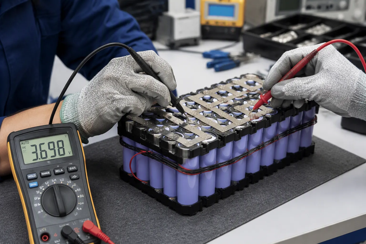
Quick Answer: A cell substitution is an engineering change, not a purchasing equivalence. Compare the exact cell model, electrical limits, dimensions, interconnects, thermal behavior, aging, gauge model and approval scope. Release the substitute only after documented change assessment and appropriate validation.
Key Takeaways
Matching capacity and voltage is only the first step. Cells with the same ratings can still act in different ways.
Check the internal resistance and self-discharge rates. These differences cause uneven current sharing and early pack failure.
Make sure the BMS can handle the limits of the new cell. The BMS must protect against overcharge and over-discharge.
Test the replacement cell carefully. Electrical, thermal, mechanical, and aging tests confirm the pack works safely.
Write down every change and get it approved. A written checklist and retest results protect your decision to release.
Part 1: Battery Cell Substitution Beyond Capacity and Voltage
1.1 What Voltage and Capacity Matching Confirms
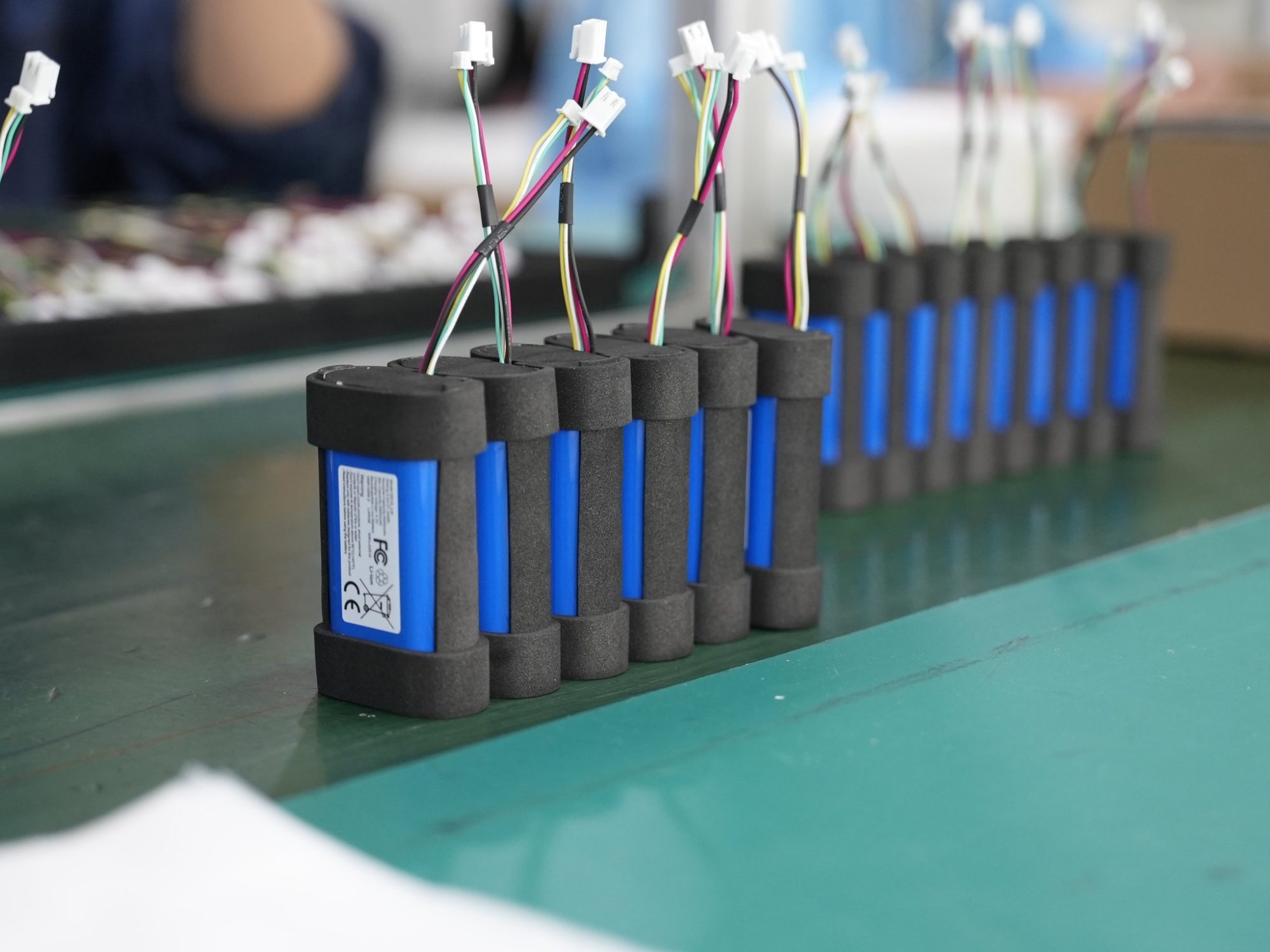
Matching nominal ratings is an initial screening step. It does not prove identical chemistry, charge limits, discharge curves or compatibility. Compare exact manufacturer part numbers and controlled datasheet revisions rather than assuming equivalent labels establish interchangeability.
Engineers must write down the exact approved cell model, its datasheet limits, and the pack’s original design assumptions before comparing any substitute. This requirement definition becomes the baseline for every later evaluation. Without this documentation, a substitute that looks equal on paper can bring unpredictable behavior into the assembled system.
Cells with similar open-circuit voltage can still differ a lot in usable capacity. A cell rated at 2000 mAh may deliver only 1900 mAh under the same discharge profile as another cell from the same production batch. This gap matters because series strings work like a chain: the weakest cell limits the entire pack’s deliverable energy. In a medical device pump or a security system backup unit, early cutoff from one weak cell forces an early recharge cycle, which reduces operational readiness.
1.2 Internal Resistance and Self-Discharge Gaps
Parallel-branch current depends on OCV, resistance, SOC, temperature and interconnect layout. Lower resistance can initially draw more current, but electrothermal behavior is dynamic and must be measured. Do not infer branch safety from aggregate pack resistance alone.
V_terminal = V_OCV − I·R_internal (discharge; resistance term reverses during charge)
P_loss = I²·R
For N identical parallel cells: R_block = R_cell / N
For dissimilar cells: 1/R_block = 1/R_1 + 1/R_2 + …
High resistance produces greater voltage sag, more heat, and reduced power capability. This becomes critical in robotics applications with high current demand during acceleration or lifting. A substitute cell with the same capacity but higher impedance changes pack behavior entirely, even though the datasheet capacity figures match.
Cell imbalance also comes from self-discharge rate differences. Cells within a pack are never identical in capacity, temperature range, impedance, and self-discharge rate. Cell balancing techniques—active or passive—help each individual cell keep enough power to do its job. However, balancing cannot make up for fundamental mismatches introduced at assembly time.
Set production matching criteria from the qualified design, measurement method, temperature, SOC and supplier capability. The numeric values in the following table are illustrative only and must not be used as universal tolerances. AC impedance and DC pulse resistance are different measurements.
Parameter | Acceptable matching range (same group) | Notes |
|---|---|---|
Capacity | Actual capacity error within 3%–5%; for 2000 mAh cells, difference ≤100 mAh | Prevents ‘weakest link’ effect and over-discharge of lower-capacity cells |
Internal resistance (AC) | Error within 5 mΩ–10 mΩ (e.g., 25/26/27 mΩ grouped together) | Large IR differences cause uneven heating and unbalanced charge rates |
In a series string, the limiting cell group can reach its discharge boundary before the rest of the pack. Verify individual group monitoring and cutoff against the selected cell limits. There is no universal 2.80 V cutoff for all lithium cells, and balancing cannot compensate for an unsuitable substitute.
Part 2: Impedance, Current Rating, and Charging Limits
2.1 Impedance Effects on Sag and Heating
Cell impedance decides how much voltage the pack loses when it is under load. A substitute with the same capacity but higher impedance changes how the pack works in several ways:
Compare DC voltage sag at the required current, temperature and SOC.
Measure I-squared-R heating for the actual pulse and continuous duty.
Check parallel current sharing using branch and interconnect resistance.
Validate aged-cell behavior and the host cutoff response.
2.2 Current Rating and Charging Limits
Continuous discharge current and peak ratings must be checked against the original approved model, not guessed from capacity. The table below shows cell-level ratings from published cell data:
Chemistry | Nominal Voltage | Capacity | Continuous Load Rating | Notes |
|---|---|---|---|---|
Discharge capability | 3.6 V/cell | Rated capacity at defined conditions | Validate actual continuous load | Verify charge current and temperature limits |
Pulse capability | 3.6 V/cell | Capacity alone is insufficient | Define pulse duration and repetition | Verify temperature-dependent current limits |
Chemistry and protection review | 3.2 V nominal; verify exact cell | Confirm exact cell revision | No chemistry-wide current rating | Validate cell and pack safety scope |
Continuous and pulse ratings are specific to a cell model, temperature, cutoff and test duration. Do not infer current capability from a generic energy or power-cell label. Verify charge voltage, current, termination, temperature limits and protection thresholds for the substitute with the actual charger and BMS.
Part 3: Mechanical Fit, Gauge Models and Charging Compatibility
3.1 Dimensions, Tolerance Stack-Up, and Gauge Profile
Check cell dimensions and tolerances, wrapper and insulation thickness, vent clearance, holders, tabs, weld geometry and assembly compression. Similar format names do not guarantee mechanical interchangeability. Fuel-gauge chemistry profiles are electrical models and must not be confused with physical fit or contact pressure.
3.2 Revalidating Charger and Host Behavior
For lithium-cell substitution, compare the maximum charge voltage, allowed charge current, termination and recharge behavior at each temperature. A substitute may require charger firmware, BMS thresholds or host changes. A connector or nominal voltage match does not authorize the existing charging algorithm.
Aspect | Review area | Required lithium-cell evidence |
|---|---|---|
Charge ceiling | Exact approved maximum charge voltage | Charger accuracy and BMS threshold review |
Charge current and temperature | Cell-specific limits | Temperature-dependent validation |
Host and gauge compatibility | Qualified charger and pack pairing | Updated SOC model and host tests |
Compare charger firmware, voltage accuracy, current limits, termination and restart conditions using an approved compatibility matrix. Do not mix substitute cells into existing packs or change field cells without a controlled manufacturing and service process.
Compare calendar aging, cycling, self-discharge and low-temperature behavior using representative data for the exact cells. Update the gauge model and validate SOC, remaining runtime and low-battery alarms in the final host.
Validate low-temperature voltage sag and capacity using the exact lithium cell and load profile. Temperature gradients can affect branch current sharing and the reliability of SOC estimates.
Neither active nor passive balancing can restore lost cell capacity or make incompatible cells interchangeable. Select the balancing strategy for the approved topology and quantify its current, operating window and energy budget.
Part 4: Safety, BMS Compatibility, and Retest Acceptance
4.1 Safety Certification Scope and BMS Compatibility
Assess the proposed change against the specific test reports, certification files, transport test type and product regulations. A cell approval does not automatically cover the changed pack, and a substitution does not automatically invalidate every approval. Obtain the applicable laboratory or certification-body decision before release. IEC 60601-1 addresses the medical device system; ISO 13485 addresses quality management, and ISO 14971 addresses device risk management.
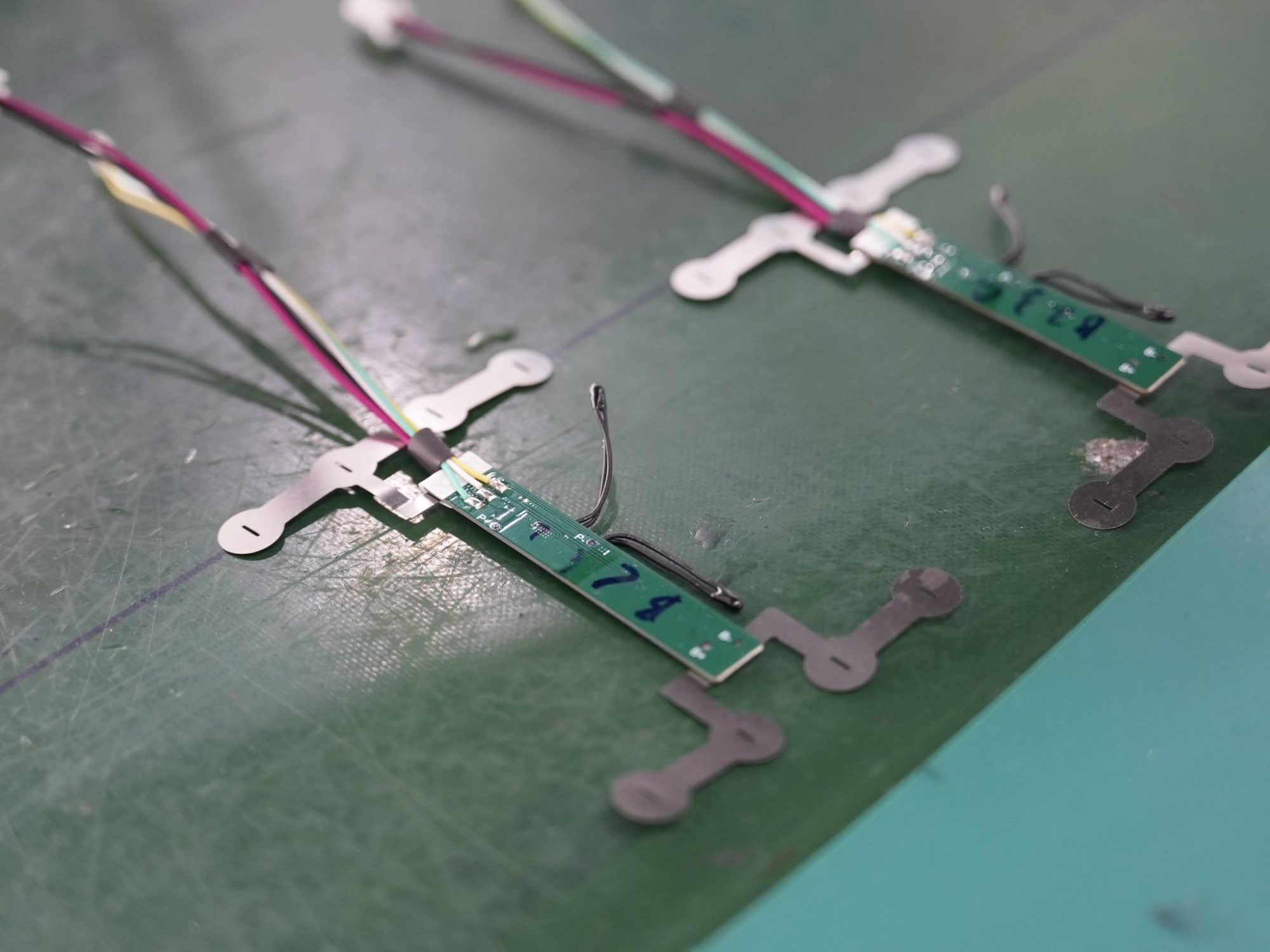
The battery management system must enforce limits the substitute cell can actually handle. Engineers should compare charge and discharge voltage ranges, not just nominal voltage. They should measure charger output for charging voltage, charging current, termination, and standby behavior with a sample pack. A full discharge test under fixture load confirms that BMS protection cutoff does not end runtime early. Cell-level voltage monitoring must be standard, because a BMS that tracks only overall pack voltage cannot prevent localized overcharge or over-discharge. Protection response times deserve explicit verification in the specification. The BMS and PCM reference covers protection thresholds and configuration in more detail.
4.2 Change Assessment and OEM Acceptance Checklist
Link the change assessment to electrical, thermal, mechanical, aging and host-interface requirements. Verify charger limits, BMS configuration, gauge parameters, communications, fault responses and production process compatibility. Define the required retests from risk and approval-scope review, and retain signed evidence tied to the released BOM revision.
Checklist item | Acceptance evidence |
|---|---|
Exact approved cell model | Manufacturer, model, datasheet revision on file |
Dimensions and gauge profile | Drawing comparison, fit sample in holder |
Impedance and current rating | Matched to original limits, load test data |
Charging limits | Charger measurement, algorithm confirmation |
BMS configuration | Threshold, monitoring, and response time records |
Change assessment and retest | Electrical, thermal, fit, aging results signed off |
Getting approval for a battery cell substitution requires a full review of electrical, mechanical, thermal, safety, and system-level factors. Matching capacity and voltage is only the first check. Engineers must look at the exact approved cell model, its datasheet limits, and the pack’s BMS configuration together. A written change assessment and clear retest acceptance criteria protect the release decision.
Review BMS and PCM settings alongside the charger and host behavior. Record the approved alternate cell, revised configuration, traceability requirements and release authorization before production.
FAQ
Why does matching capacity and voltage fail as an approval test?
Matching capacity and voltage only confirms the first basic check. Cells with similar open-circuit voltage still differ in usable capacity, impedance, and self-discharge rate. These gaps cause uneven current sharing and weak-cell reversal under load. The bms cannot fix a basic mismatch that was built in at assembly.
What impedance checks should a substitute cell pass?
Compare AC impedance and DC pulse resistance using defined temperature, SOC and timing conditions. Set acceptance limits from the approved design and current-sharing validation, not a universal percentage above the group average.
How can a lithium cell change affect charging and SOC reporting?
Changing a lithium cell can alter the required charge voltage, current, temperature window, gauge model and cutoff behavior. Verify all of these with the actual charger and BMS; nominal voltage alone is insufficient.
Which retests does a cell substitution require?
Retesting covers electrical, thermal, mechanical fit, and aging performance. Electrical tests check capacity, impedance, and voltage sag under rated load. Thermal tests compare charge and discharge temperature against the site profile. The bms configuration and response times need clear verification.
What belongs on the OEM acceptance checklist?
The checklist records the exact approved cell model, datasheet revision, dimensions, gauge profile, impedance, current rating, and charging limits. It also captures bms threshold records, monitoring behavior, and response times. Signed retest results close the change assessment. A battery expert or pack integrator can define the requirements and plan retesting before release.


