

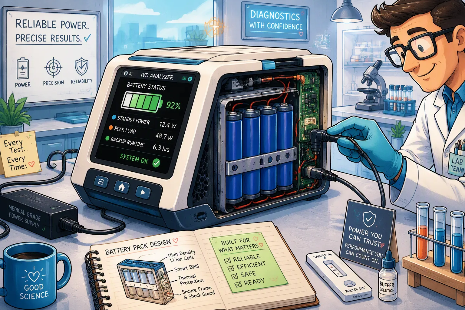
A portable IVD analyzer may spend hours waiting between tests, then draw substantially more power for sample handling, temperature control, optical measurement or data transmission. Its battery must support this complete sequence, not just the average load. If external power fails, the required response may be completing the current assay, preserving data or continuing a defined number of tests.
Engineering custom lithium battery packs for these instruments starts with three separate budgets: standby drain, peak-load capability and usable backup energy. The cell, BMS and host power architecture need to satisfy all three together.
Quick Answer: Measure battery-side consumption in each operating mode, record worst-case pulse current and duration, and define what must continue after external power loss. Select a pack voltage range compatible with the analyzer, then size energy for conversion losses, aging, temperature and reserve. Validate the complete analyzer with realistic assay profiles rather than assuming a particular topology guarantees runtime.
Key Takeaways
Separate shipping, powered-off storage, sleep and ready-to-test standby.
Calculate electronic drain in amp-hours; evaluate chemical self-discharge separately.
Choose series and parallel counts from voltage range, energy and current requirements.
A parallel cell group is not an independent backup power source.
Validate test completion, data integrity and alarms at the specified end-of-service battery condition.
Part1: Build a Mode-Based Power Budget
1.1 Define the Analyzer’s Actual Operating States
Standby can mean a sleeping controller or a temperature-controlled instrument ready to start immediately. These states have very different demands. Define the required wake-up time, retained data, clock function and communication behavior for each mode. Battery storage requirements must come from the product’s intended distribution and service cycle, not an assumed 12–24-month shelf life borrowed from another component.
Mode | Potential loads | Design question |
|---|---|---|
Shipping or long storage | Residual protection and leakage | What charge remains after the specified storage interval? |
Sleep | Wake circuitry, clock, gauge and periodic checks | How quickly and reliably must the analyzer wake? |
Ready standby | Controller, display, connectivity and possible thermal control | Which functions must remain active? |
Assay | Heaters, motors, optics, processing and pumps where present | Which loads overlap and determine the peak? |
Backup operation | Defined assay and data-preservation functions | What must continue after external power loss? |
1.2 Calculate Electronic Drain Correctly
For a constant current drawn directly from the pack, Qlost (Ah) = I (A) × time (h). As an illustrative calculation, 10 µA over 8,760 hours consumes 0.0876 Ah, or 1.75% of a 5 Ah pack. At 1 µA over 720 hours, drain is 0.00072 Ah, or 0.0144% of that capacity. These figures exclude self-discharge and all other loads.
For loads behind converters, include conversion efficiency and quiescent losses. Measure average battery-side current over periodic wake cycles, not only the quiet interval. Include the protection IC, gauge, host leakage, charger reverse leakage, divider networks, indicators and any balancing activity. In series packs, unequal monitoring drain can create imbalance even when overall current seems small.
1.3 Treat Self-Discharge as a Separate Mechanism
Electronic leakage and chemical self-discharge are different. Self-discharge depends on the specific cell, storage temperature, SOC, age and condition. Do not assign a universal monthly percentage to NMC or LFP, or extrapolate a short test into years of storage without supporting evidence. Calendar aging also reduces deliverable capacity and is not identical to reversible charge loss.
Establish storage tests at the intended conditions. Measure retained charge, recoverable capacity after recharge, voltage spread and wake-up behavior. Specify initial storage SOC, recharge intervals and the minimum condition needed for shipment or service.
Part2: Reduce Standby Drain Without Losing Readiness
2.1 Verify Sleep and Ship Mode at System Level
Sleep and ship-mode functions are device-specific. A low-power monitor state does not necessarily disconnect the load, and a load-disconnect state does not eliminate cell self-discharge or internal drain. Verify the complete schematic, protection behavior, wake source and temperature-dependent leakage.
Load switches can isolate display, radio and other nonessential domains. Retain only functions justified by the operating requirements. Check that communication or measurement pins cannot unintentionally back-power a disconnected domain. Confirm recovery with a depleted pack and after long storage.
2.2 Measure the Whole Assembly
Test on representative production assemblies with the intended firmware and accessories. PCB contamination, humidity and component tolerances can affect leakage. Cleaning or coating controls should be qualified for the application rather than assumed to guarantee low current.
Use instrumentation suitable for both small standby currents and larger wake pulses. Measure over enough time to capture periodic monitoring and communication. TI’s medical design resources identify low-quiescent-current electronics as one route to longer battery life; the actual analyzer budget still requires measurement.
Part3: Design for Peak Loads and Voltage Sag
3.1 Characterize Current at the Battery Terminals
Record amplitude, duration, repetition rate, start-up inrush and simultaneous loads. A heater or motor demand is not interchangeable with a short measurement pulse. Include the lowest supported pack voltage: a constant-power load generally draws more current as voltage decreases.
C-rate = current (A) / capacity (Ah), evaluated at the correct level. For example, a 5 A pack load with two ideally sharing 2.5 Ah cells in each parallel group gives 2.5 A per cell, approximately 1C. Real sharing depends on resistance and interconnect symmetry. Use model-specific continuous and pulse limits, including pulse duration, rest periods, SOC and temperature.
3.2 Select Voltage and Topology from Requirements
A 5S2P pack contains five series-connected groups with two cells in parallel per group, ten cells total. With cells rated 3.6–3.7 V nominal and 4.2 V maximum, nominal pack voltage is 18.0–18.5 V and maximum is 21.0 V. These values do not apply to a different chemistry. The analyzer must accept the entire qualified discharge-to-charge voltage range.
Parallel cells can increase capacity and reduce equivalent group resistance, but they do not create two independently protected backup packs. A cell short, shared BMS failure or common connector fault can affect the whole assembly. Any redundancy claim requires separately analyzed power paths and fault isolation.
Estimate sag from I × R, including cell groups, wiring, fuse, FETs and connectors, then measure it dynamically. Parallel count must meet both energy and thermal/current requirements. The BMS must protect each series group without nuisance trips during qualified load transients.
3.3 Add Pulse Buffering Only When Justified
A capacitor or supercapacitor can support a short transient, but needs a designed charging path, voltage compatibility and inrush control. For an approximately constant capacitor current, C ≥ I × Δt / ΔV. A 5 A, 0.5 s pulse with 1 V permitted capacitive droop needs at least 2.5 F ideally, before ESR, tolerances, aging and temperature margins. The initial ESR drop is additional.
Do not connect a supercapacitor directly across a battery without evaluating its voltage rating, surge current, balancing needs and fault behavior. Compare buffering against using a better-suited cell or increasing parallel count.
Part4: Size Backup Energy for a Defined Workflow
4.1 Specify the Required Outcome
Define whether backup must complete one assay, support a time window, preserve results or maintain thermal control. Specify the assay type, initial charge condition, required alarms and behavior if there is insufficient reserve to start another test. A universal two-hour backup requirement or 80% DoD rule is not appropriate for every analyzer.
Energy at the load is Eload (Wh) = integral of power over time. For a simplified steady case, 15 W for two hours requires 30 Wh at the load. At 90% conversion efficiency, battery-delivered energy is about 33.3 Wh before reserve and derating. Amp-hours multiplied by time are not watt-hours; voltage must be included when converting charge capacity to energy.
4.2 Apply Explicit, Validated Margins
As an illustrative preliminary model, if only 80% of rated energy remains at end of service and 90% of that is accessible within the qualified voltage/load window, rated energy would need at least 30 / (0.90 × 0.80 × 0.90) ≈ 46.3 Wh. Add any separate assay-completion reserve and justified temperature margin. These factors are design assumptions, not universal battery ratings, and must not double-count effects already captured in measured usable energy.
For pulsed workflows, remaining test count or a conservative completion indicator may be more useful than SOC alone. TI’s pulsed-load gauging discussion highlights the distinction between remaining charge and useful pulses. Configure and validate the gauge for the actual cell and assay profile.
Part5: Validate the Analyzer and Applicable Standards
5.1 Test the Complete Power Architecture
Test | Pass criteria to define |
|---|---|
Long storage and wake-up | Retained energy, reliable wake and safe recharge. |
Worst-case assay loads | Rail stability, acceptable temperatures and no unintended reset. |
External source loss and recovery | Required assay behavior, data integrity and controlled source transfer. |
Aged and temperature-conditioned packs | Required usable energy and pulse capability at specified limits. |
Gauge, sensor and communication faults | Appropriate alarms and controlled operating restrictions. |
Firmware and component changes | Repeat affected standby, peak-load and backup tests. |
Record pack revision, cell lot, firmware, SOC preparation, conditioning, load profile and cutoff criteria. Use complete-analyzer testing to confirm analytical performance where power disturbances could affect measurement; a programmable load alone cannot establish result accuracy.
5.2 Avoid the Wrong Compliance Assumption
IVD equipment requires a product-specific standards assessment. IEC 61010-2-101 addresses IVD medical equipment and is intended for use with IEC 61010-1. Do not automatically present IEC 60601-1 as the governing standard merely because the analyzer is used in healthcare. Confirm applicable editions and market requirements with the device’s compliance team.
Battery safety and transport requirements, such as IEC 62133-2, UL 2054 and UN 38.3 where applicable, address different scopes. ISO 13485 concerns quality management, not a guaranteed runtime. Link battery qualification and change-control evidence to the device validation plan.
For IVD analyzer battery integration, provide mode currents, pulse traces, input voltage limits and the required backup workflow. Request a custom battery review before fixing the pack layout and interface.
FAQ
Is 5S2P suitable for every portable IVD analyzer?
No. Select topology from the full input voltage range, energy, peak current, enclosure and thermal requirements. 5S2P is one possible configuration, not a standard platform.
Does ship mode guarantee years of storage?
No. Verify residual drain, cell self-discharge, calendar aging, wake-up and the remaining usable energy over the specified interval.
Should NMC self-discharge be assumed to be 20–40% per month?
No. That is not a sound general design assumption. Obtain model-specific evidence and test the complete assembly under the intended storage conditions.
Does adding parallel cells provide backup redundancy?
No. It increases capacity and current-sharing capability. Independent backup requires analyzed source paths, protection and fault isolation.
Must the design use an 80% DoD limit?
No. Choose the usable operating window from cell limits, service life, load voltage requirements and reserve policy, then validate it.
What changes require runtime revalidation?
Assess changes to cells, pack protection, connectors, converters, firmware and assay operation. Repeat tests affected by altered drain, peak loads, cutoff behavior or source switching.


