

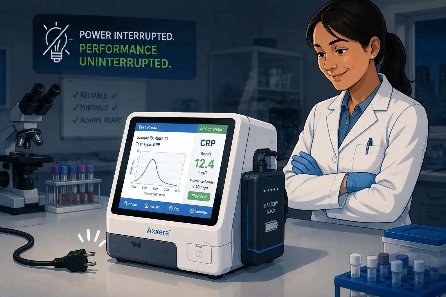
Quick Answer: First define what the IVD analyzer must do if power fails mid-assay: complete the run, preserve results and state, or stop safely. Size the backup battery for the loads and time required by that outcome, then verify it by interrupting power at representative assay stages.
Key Takeaways
Match each test step to the power it really needs. Then decide whether to keep going, save where you are, or shut down safely.
Pick a battery type and BMS features that fit your analyzer’s power use and assay integrity needs.
Size the backup energy for standby drain, peak loads, and runtime by using a mode-based power budget.
Test your power setup with interruption tests at every assay stage. Also test at the start and end of pack life.
Follow IEC 62133 and keep your battery pack in good shape with regular tests and approved chargers.
Part1: Protecting an Assay During a Power Interruption: Requirements and Failure Modes

1.1 Essential Loads by Assay Stage
You cannot pick the right size for a battery pack until you know which loads must stay on. List every load and the assay stage it serves. Then decide which loads ride through and which ones you can shed.
Assay stage | Essential loads | Ride through or shed |
|---|---|---|
Reagent handling | Reagent pumps, valves, position sensors | Ride through |
Incubation | Heater control, temperature sensors | Ride through |
Detection | Optics, photodetectors, signal processing | Ride through |
Data logging | Memory writes, result storage | Ride through |
Cold storage | Sample and reagent cooling | Ride through, or shed briefly if thermal mass holds |
The assay stage also decides the outcome. During reagent handling or incubation, a short interruption may let the analyzer finish the assay. During detection, saving state and resuming often protects the result better. Late in a run, a safe shutdown may be the only honest option. Write down this mapping for every stage, because it drives the backup energy you need.
1.2 Power Interruption Failure Modes
An outage is only one failure mode. Brownouts drop voltage without a full loss. Voltage sags last milliseconds and can reset a controller. Transfer events between mains and generator bring in switching transients. Each one puts different stress on the analyzer, and each one can corrupt an assay in progress.
A voltage stabilizer or surge protector between the outlet and the analyzer is a low-cost first-line upgrade. It soaks up transients and trims sags before they reach the power supply. It does not replace a battery pack, but it cuts how often the pack must carry the load. Treat it as the first layer of Protecting an Assay During a Power Interruption, with the lithium pack as the second.
Part2: Lithium Battery Chemistry and BMS Selection
2.1 Matching LCO, NMC, LiFePO4, and LMO
The chemistry you pick sets the energy density, cycle life, and voltage platform your pack can offer. The table below shows cell-level reference ranges. Use them as cell guidance, not as pack guarantees, because pack design, thermal control, and depth of discharge all change the real numbers.
Chemistry | Platform voltage | Energy density (Wh/kg) | Cycles |
|---|---|---|---|
LCO | 3.7 V | 180–230 | 500–1,000 |
NMC | 3.6–3.7 V | 160–270 | 500–1,000 |
LiFePO4 | 3.2 V | 100–180 | 2,000–5,000 |
LMO | 3.7 V | 120–170 | 300–700 |
Each chemistry fits a certain use best. LCO works well for compact, high-density designs like handheld and wearable devices, per Verified Market Reports. NMC balances energy density, lifespan, and cost, so it suits electric vehicles and grid storage. LMO serves power tools, e-bikes, and some medical devices where safety and cost matter. LiFePO4 gives long cycle life and steady performance in demanding duty. BateriaPower notes that LiFePO4 packs back up data centers, hospital emergency systems, and portable power banks. Solid-state and lithium-metal cells are a forward-looking option for space-constrained analyzers.
For a portable IVD analyzer, match the chemistry to the load profile. A benchtop unit that cycles often may favor LiFePO4. A handheld unit with tight weight limits may favor NMC or LCO. Medical devices already rely on small Li-ion cells for portable diagnostic tools, where safety and longevity come first, according to Verified Market Reports.
2.2 BMS Functions for Assay Integrity
The battery management system turns a cell stack into a protected, predictable power source. Three functions matter most for assay integrity.
Sleep mode cuts standby drain when the analyzer sits idle between runs, so the pack keeps charge for the next interruption.
Protection blocks overcharge, overdischarge, overcurrent, and short circuits before they damage cells or drop the rail mid-assay.
Monitoring tracks cell voltage, current, and temperature, and it reports state of charge so the analyzer knows how much runtime is left.
These functions deserve careful specification. Our guide to BMS and PCM design covers the architecture in depth. Industry shows the payoff. KUKA reports that robots now assemble and inspect battery management systems for electric vehicles, which shows how mature this electronics supply chain has become. Healthcare facilities also depend on stable environmental controls, and a well-monitored pack plays the same role inside your analyzer.
Part3: Backup Design: Power Budgeting and Runtime Sizing
3.1 Mode-Based Budgeting and Standby Drain
Begin your power budget by measuring how much the battery uses in each operating mode. Record the current draw during reagent handling, incubation, detection, and idle. Each mode gives you one number, and together these numbers show where the pack energy really goes.
Standby drain needs its own line. An analyzer can sit idle for weeks between runs, and a small leakage current adds up over time. The large-battery.com blog on portable IVD analyzer pack design gives a worked example. A draw of 10 µA over 8,760 hours uses 0.0876 Ah, or 1.75% of a 5 Ah pack. A draw of 1 µA over 720 hours drains 0.00072 Ah, or 0.0144% of that capacity. Both figures leave out self-discharge and other loads, so treat them as a floor.
BMS sleep mode is your main lever here. The management system shuts down monitoring circuits and wakes on a trigger, which cuts idle drain before it eats your reserve. Set the sleep threshold and wake condition with the assay schedule in mind, so the pack stays ready for the next interruption.
3.2 Peak Loads and Backup Energy Sizing
Peak loads and total energy are different problems, and one pack must solve both. A 5S2P topology helps here. Five cells in series raise the pack voltage, and two parallel strings share the current. Each string carries half the load, so the pack handles a current pulse that a single string could not. The parallel pair also adds capacity, which extends runtime.
For short transients, a capacitor or supercapacitor can buffer the pulse. The large-battery.com blog gives the relation: capacitance must be at least pulse current times pulse duration divided by permitted voltage droop. A 5 A, 0.5 s pulse with 1 V of permitted droop needs at least 2.5 F ideally, before ESR, tolerances, aging, and temperature margins.
Now size the energy. The blog works a steady case of 15 W for two hours, which requires 30 Wh at the load. At 90% conversion efficiency, the battery must deliver about 33.3 Wh before reserve and derating. Add clear margins. If only 80% of rated energy remains at end of service, and 90% of that is accessible within the qualified voltage and load window, rated energy must reach at least 30 / (0.90 × 0.80 × 0.90) ≈ 46.3 Wh. Add any separate assay-completion reserve and a justified temperature margin on top.
Do not copy a universal two-hour rule or a fixed 80% depth-of-discharge limit onto every analyzer. Define what the backup must do: complete one assay, hold a time window, preserve results, or keep thermal control. Size standby drain, peak capability, and usable backup energy together against that definition.
Part4: Validating the Power Architecture Against Standards
4.1 Validating Assay Protection During Interruptions
Testing shows that the design really works. Make an interruption test plan that matches your assay stages. Cut the main power during reagent handling and check that the analyzer finishes the run. Cut power during detection and check that it saves its state and resumes with a good result. Stop a late-stage run and check for a safe shutdown with no damaged data.
Run each test for every failure mode from Part1. A full outage, a brownout, a quick voltage sag, and a mains-to-generator transfer each put different stress on the pack. Write down the pack voltage, the rail voltage, and the assay result for every trial. Run the tests at the start and end of pack service life, because an old pack holds less reserve.
Write down the complete, save-state, or safe-shutdown behavior for each stage. This record becomes your proof that Protecting an Assay During a Power Interruption holds under real conditions, not just on paper.
4.2 Standards, Maintenance, and Data Integrity
IEC 62133-2 covers safety for portable sealed secondary cells and batteries. Design your lithium pack to meet it, and keep the test reports with your design history file. Pair it with your regional medical device electrical safety rules and your quality management system records.
Maintenance keeps the protection working over the analyzer’s life:
Keep backup batteries fully charged between runs.
Test the pack on a fixed schedule and log the results.
Use only manufacturer-approved chargers and accessories.
Get cold storage ready for samples and reagents before an outage threatens them.
Data integrity depends on all four. A pack that passes its interruption test today can fail next year without scheduled checks. Treat the battery as a validated subsystem, not a consumable you replace when it dies.
Protecting an Assay During a Power Interruption follows one chain. You define essential loads and failure modes first. Then you choose chemistry and BMS functions. Next you size backup energy for standby drain, peak loads, and runtime. Finally you validate the whole design against standards. Assay protection is an architecture decision, not a single component choice. Document the complete, save-state, or safe-shutdown mapping for every assay stage.
Give lab managers and biomedical engineers this checklist:
Add surge protection between the outlet and the analyzer.
Keep backup batteries fully charged and test them on a schedule.
Use only manufacturer-approved chargers and accessories.
Run interruption tests at each assay stage, at the start and end of pack life.
FAQ
Which assay stages need full battery ride-through?
Reagent handling, incubation, detection, and data logging all need ride-through. Cold storage can shed briefly if thermal mass holds. Map each load to its stage before you size the pack. That mapping is the first step in Protecting an Assay During a Power Interruption.
How do I choose between finishing, saving state, and safe shutdown?
Let the assay stage decide. Early stages can often finish on backup power. Detection benefits from saving state and resuming. Late-stage runs may call for a safe shutdown. Document the choice for every stage.
Does a surge protector remove the need for a battery pack?
No. A surge protector or voltage stabilizer trims transients and sags before they reach the power supply. It cuts how often the pack must carry the load. It cannot finish an assay on its own.
Why does a 5S2P pack help with peak loads?
Five cells in series raise pack voltage. Two parallel strings share the current, so each string carries half the load. The parallel pair also adds capacity. A capacitor can buffer short pulses on top of that.
Which standard covers lithium pack safety?
IEC 62133-2 covers safety for portable sealed secondary cells and batteries. Design your pack to meet it and keep the test reports in your design history file. Pair it with your regional medical device electrical safety rules.
How often should I test the backup battery?
Set a fixed test schedule and log every result. Run interruption tests at the start and end of pack service life, because an old pack holds less reserve. Keep the pack fully charged between runs.


