

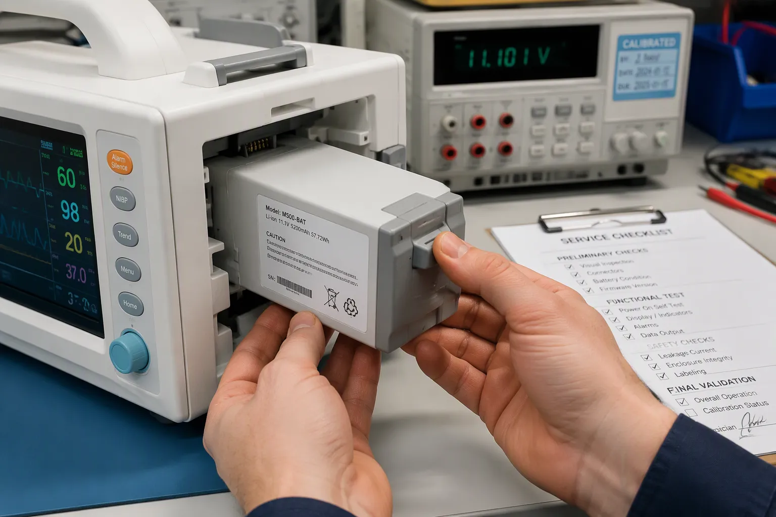
Quick Answer: Replaceable medical batteries in portable devices need careful design for mechanical retention, user error prevention, and service validation. These three elements work together to support safety and reliability.
Engineers and quality teams face three main questions. Which retention designs stop accidental disconnection? Which user errors happen during replacement? How do service procedures get validation for compliance? This post is for OEM/ODM engineers, purchasing staff, and quality teams. Medical devices are still the main focus. Robotics, security systems, infrastructure, and industrial applications appear only where relevant. The discussion covers custom lithium battery packs. It does not mean hot-swap capability unless the device architecture supports it. A portable medical device needs a reliable power source, and the pack interface decides whether that source holds up under real use.
Key Takeaways
Set retention and replacement requirements for the intended users.
Use keying and electrical safeguards to reduce foreseeable installation errors.
Validate contact continuity, wear and cleaning compatibility.
Separate routine replacement checks from design-change revalidation.
Do not imply hot-swap capability without a validated power-path architecture.
Part 1: Mechanical Retention for Replaceable Medical Batteries
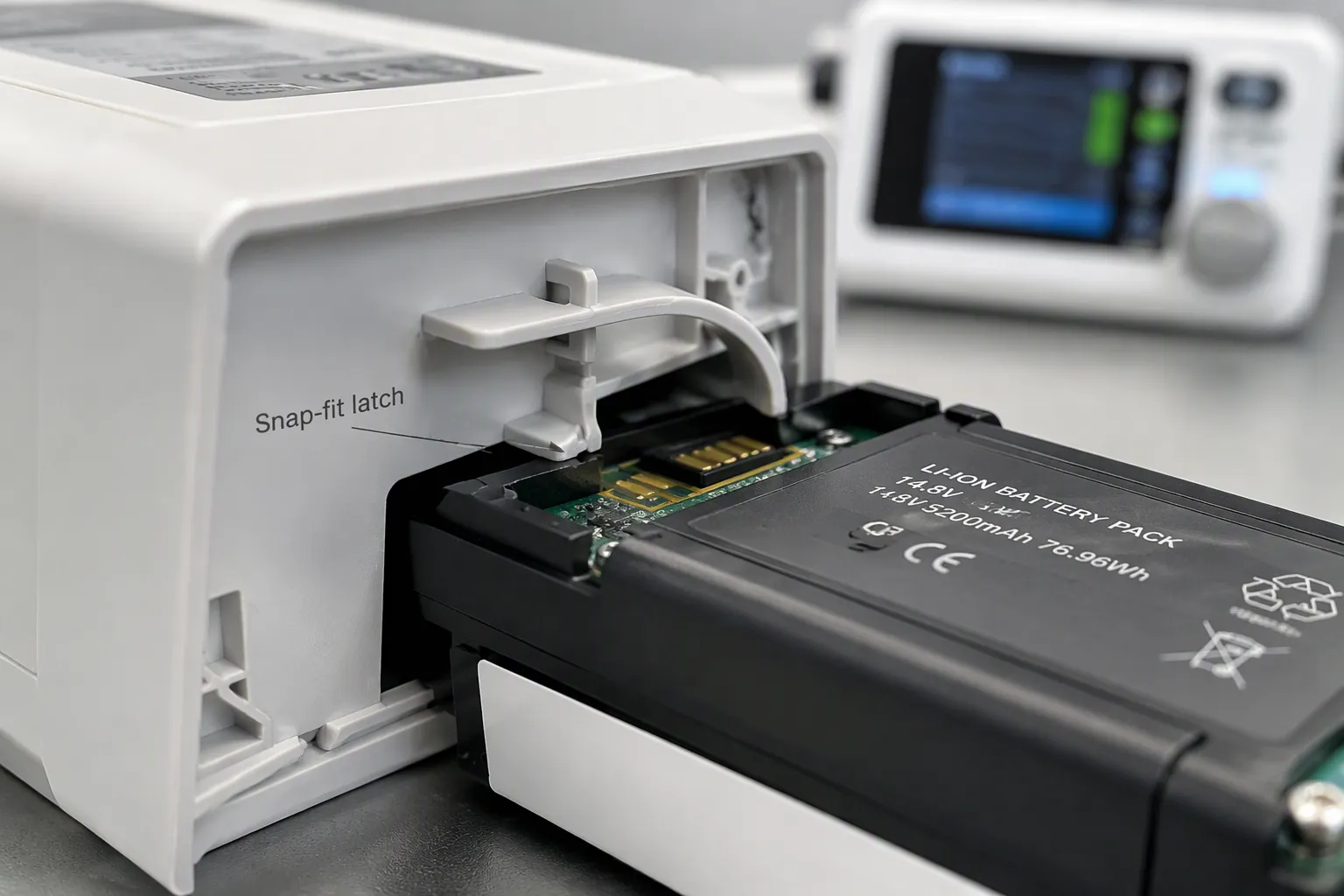
Define whether replacement is performed by the patient, a caregiver, a clinical user or trained service personnel, and whether the device must be shut down first. Specify retention, insertion and release forces, allowable interruption, connector sequencing, cleaning exposure and intended lifetime. A latch should transfer retention loads through the intended enclosure structure rather than relying on electrical contacts. Coordinate mechanical and electrical interfaces with the BMS and PCM design; neither can compensate for every partial connection or accidental removal.
1.1 Latch and Locking Mechanisms
The latch design must balance three competing needs: retention force, insertion force, and serviceability. Retention force and assembly strain link directly through undercut depth. A deeper undercut increases pull-out resistance but forces the beam to bend further during insertion, raising strain. The practical design rule keeps beam deflection within the material’s allowable strain, so latch stiffness cannot rise without limit without risking insertion damage or fracture.
Evaluate latch geometry and material together using strain, creep, fatigue and tolerance analysis. Longer or thinner arms can reduce insertion force but may also reduce stiffness or retention. Do not assign a resin from a generic material-family list: exact grade, reinforcement, molding direction, cleaning chemicals and environmental aging affect durability. Validate production-equivalent parts after representative replacement cycles, contamination and handling exposure.
Specify insertion, release and retention forces for the intended users, including gloved operation where relevant. Determine angles and clearances from material data, tolerance analysis and prototype testing rather than universal dimensions. Positive retention can reduce accidental release, but no latch alone guarantees uninterrupted power.
1.2 Tolerance, Wear, and Shock Testing
Define tolerances using the actual resin, molding process, environmental exposure and supplier capability. Evaluate latch wear, creep, seal compression and connector alignment over the intended insertion cycles. A particular spring design does not automatically compensate for all wear or misalignment.
Self-alignment and floating tolerance help blind-mate connectors engage correctly when the removable module does not enter its enclosure in the same position every time. A defined floating range allows part of the connector interface to move within specified limits, accommodating small positional differences between the battery module and the fixed interface. This floating tolerance must not replace proper mechanical design; guides, enclosure tolerances, and insertion path must keep the interface within the connector’s specified alignment range.
Set shock and vibration tests from the device use environment and risk analysis. Check retention and electrical continuity before and after repeated replacement and cleaning exposure. Choose fillets, wall geometry and material strain limits from the actual design and validate production-equivalent parts rather than using a universal dimension rule.
Validate fit using representative prototypes, then repeat retention and durability testing on production-equivalent materials and tooling. Printed prototypes do not establish molded-part fatigue life. Include connector continuity, contact resistance and host power behavior under shock and motion; review the BMS and PCM interface.
Part 2: Keying and Connector Durability
2.1 Polarity Keying and Misinsertion Prevention
Mechanical keying reduces misinsertion risk but cannot make every misuse impossible. Validate foreseeable forcing, partial insertion and damaged keys, and use appropriate electrical protection. A matching connector shell does not establish pack compatibility.
Define the replacement user and setting before designing keying and guides. Clinical technicians, home caregivers and service personnel have different access and usability needs. Validate correct installation and foreseeable errors under representative lighting, handling and cleaning conditions.
2.2 Connector Cycle Life and Cleaning
Specify mating cycles from expected replacement frequency and service life, with a justified margin. Verify contact resistance, temperature rise, retention and communication after cycling with representative contamination and cleaning exposure. A catalogue cycle rating alone does not qualify the complete interface.
Specify the actual cleaning agent, concentration, contact time, wipe method, drying conditions and number of cycles. Assess housings, labels, seals, adhesives and contacts for degradation and residual contamination. A rechargeable pack is not automatically compatible with steam sterilization or immersion. If the approved workflow requires pack removal before cleaning or drying before reinsertion, include those tasks in the usability and service validation.
Part 3: Replacement Errors and Design Mitigations
3.1 Common Replacement Errors
Include wrong-pack insertion, reversed or partial insertion, incomplete locking, damaged contacts and incompatible charging in the risk assessment. These are foreseeable error categories, not a ranked field-failure statistic. Evaluate the device response to each without assuming pack protection can compensate for every misuse.
For user-replaceable packs, validate the workflow with the intended patient, caregiver or technician group. For service-only packs, control access and instructions accordingly. Define how interrupted therapy or monitoring is handled before allowing a replacement operation.
Build a task-based use-risk analysis covering selection of the approved spare, removal, orientation, insertion, locking, status confirmation and response to a rejected or depleted pack. Include incomplete seating, interrupted communications, conductive contamination and forced insertion where foreseeable. Link each hazardous situation to a control and evidence of its effectiveness. Instructions and training support the design; they should not be the only response when a practical design change can reduce a serious use-related risk.
3.2 Labeling and Design Solutions
Use complementary safeguards such as keying, guides, retention feedback, compatible-pack identification and charging interlocks where justified. Mechanical fit cannot prove authenticity or electrical compatibility. Test both correct installation and foreseeable misuse without imposing excessive force or unsafe workarounds.
Provide approved pack identification, orientation, lock indication and service instructions appropriate to the device. Define replacement criteria from validated runtime and condition, not a universal swap interval. BMS identity and charge reporting can support checks but do not replace independent protection and host validation.
Validate usability with intended users performing representative replacement tasks in the intended setting, including gloves, limited visibility or time pressure where relevant. Do not coach users through critical tasks and treat successful engineering bench insertion as a substitute for human-factors validation. Record use errors, close calls and task difficulties, investigate their causes and evaluate whether additional design controls are needed. FDA human-factors considerations include maintenance tasks such as battery replacement.
Part 4: Service Replacement and Change Validation
4.1 Validation and Training
Separate user replacement from service-only replacement in the approved procedure. Identify compatible pack revisions, isolation or shutdown steps, seating and lock checks, status checks and the required post-replacement functional test. Torque applies only to specified fasteners, not every latch. Where replacement could interrupt therapy or monitoring, define an approved alternate-power or safe-stop workflow. Risk management and applicable device standards establish acceptance criteria; the pack supplier provides supporting interface, verification and traceability data.
4.2 Compliance and OEM Checklist
Determine applicable device, battery and market requirements with the regulatory team. Do not assume a generic lithium-content threshold defines whether a rechargeable pack may be replaced. Assess cell or interface changes against specific report and certification scope, and document whether additional testing or approval is required.
Gate | Buyer-side item | Supplier-side item |
|---|---|---|
Requirements | Load profile, environment, lifetime target | Feasibility and risk list |
Design | Envelope, connector, BOM limits | DFM proposal, control plan |
Prototype | Sample quantity, test plan | Lot traceability records |
Testing | Performance and reliability plan | Failure analysis, corrective actions |
Production | Forecast, incoming inspection | SPC records, change control |
Distinguish design validation from routine replacement checks. Validate the replacement procedure during development, then perform the documented seating and functional checks after each approved service replacement. A like-for-like replacement does not automatically require repeating full product qualification. Changed cells, firmware or interfaces require a separate change-impact assessment.
Verify retention and electrical continuity under the defined use environment, and validate connector wear and cleaning compatibility. Replacement instructions and checks must match the approved service model. Do not describe the pack as hot-swappable unless power-path behavior and essential performance during replacement have been validated.
OEM/ODM engineers, purchasing, and quality teams should set requirements early, discuss design tradeoffs openly, and agree on test acceptance criteria before tooling. These practices keep replaceable medical batteries reliable in medical devices. A custom lipo battery pack earns trust through documented validation, not guesswork.
Before release, reconcile the drawings, pack and charger identifiers, risk controls, cleaning instructions, verification results and approved service procedure. Define complaint and field-return feedback so retention wear, use difficulties and unexpected power interruptions trigger a documented review.
FAQ
Why can’t a friction fit alone hold a replaceable lithium battery pack?
Friction varies with tolerance, wear, contamination and temperature, so a nominal pull-force measurement is not enough. A positive latch is one possible risk control, not a universal regulatory requirement or a guarantee against release. Select the retention architecture from the use-risk analysis and demonstrate retention and electrical continuity after aging, cleaning and representative shock or movement.
How many mating cycles should a pack connector be rated for?
The device’s defined use environment sets the number. A hospital fleet that swaps packs often needs a higher rating than a home-use device with occasional replacement. The pack specification should document rated mating cycles and how contact resistance behaves after cycling. Engineers should not assume one number works for every device.
What makes an unauthorized battery or charger a safety concern?
Compatibility is not established by connector fit or nominal voltage. An unsuitable charger, missing protection or incorrect communication can create hazards. Use the approved pack and charger combination and validate rejection or safe handling of incompatible items.
Does service replacement require revalidation?
Validate the replacement workflow during development and specify checks after each service replacement. Full design revalidation depends on whether the replacement changes the approved design or risk assumptions. Like-for-like service and a redesigned battery are not the same event.
Which standards frame retention and replacement validation?
Use ISO 14971 for device risk management and IEC 60601-1 where applicable for basic safety and essential performance. Confirm relevant particular standards, usability, battery safety and transport requirements with the device regulatory team. No generic lithium-content threshold establishes replacement compliance.


