

Choosing a power supply and DC-DC converter for a battery-powered device involves more than matching voltage and wattage ratings. The battery voltage changes as it charges and discharges, while the equipment may draw much more current at startup than it does during normal operation. A converter that looks suitable on paper may struggle when the battery is nearly depleted, and a power supply with the right output voltage may still be unsuitable for charging the pack.
The selection process starts with the battery’s actual voltage range and the load’s power demands, then works through charging requirements, converter ratings and system-level testing. A 12.8 V LiFePO4 pack provides a practical example of how these factors affect component selection.
1. Establish the battery and load requirements
Start from the pack’s real behavior and the load’s real demand:
- Voltage range. Use the full range between the BMS cutoff and the full-charge voltage, not the nominal figure. Loaded sag pushes the low end lower still.
- Charging limits. Note the termination voltage, the maximum charge current and the allowed charging temperature range.
- Load profile. Continuous power matters, but the short startup or peak demand is usually what stresses the system.
Then ask a question that can remove a component: can the equipment accept the pack’s full voltage range directly? If so, you may not need a converter at all, which removes a cost, a loss and a failure point.
If it cannot, calculate the current the pack must deliver. It is highest when pack voltage is lowest, and it drives the BMS, fuse and wiring choices.
In the example, the pack and load are:
| Item | Assumption |
|---|---|
| Pack | 4-cell LiFePO4, 12.8 V nominal, 20 Ah (about 256 Wh) |
| Voltage range | About 10 V (BMS cutoff, 2.5 V per cell) to 14.4 V (full charge, 3.6 V per cell) |
| Charging | Up to 10 A (0.5C), constant current then constant voltage at 14.4 V |
| Load | Regulated 12 V: 60 W continuous (5 A), 15 A (180 W) for 200 ms at startup |
Assuming 90% converter efficiency, the continuous draw at 10 V is 60 ÷ (0.9 × 10) = 6.7 A, against 4.6 A at 14.4 V. The startup surge at 10 V is 180 ÷ (0.9 × 10) = 20 A. The battery, BMS, fuse, wiring and converter input must all tolerate that demand at the lowest pack voltage.
A note on capacity: 256 Wh is theoretical energy at nominal voltage. Real runtime is lower, depending on the discharge cutoff, converter efficiency, temperature, cell aging and BMS settings.
2. Match the charging source to the battery
A battery is not a load that accepts whatever voltage you give it. Lithium packs expect a defined charge profile: a current-limited phase, then a constant-voltage phase at the manufacturer’s termination voltage, with the current held within what the cells and BMS allow. Charging must stay within the cell or pack manufacturer’s specified temperature limits, with low-temperature charge protection where required, and the BMS should not be assumed to provide it. Minimum charging temperatures differ between cells, BMS designs and packs, so follow the range your battery manufacturer specifies rather than assuming a generic figure.
This is why a supply whose output voltage “looks right” can still be wrong, and why three things that are often confused should be kept apart:
- AC-DC power supply: provides DC output, but does not necessarily include battery charge control or termination logic.
- Battery charger: controls charge voltage, current and termination according to the battery’s requirements.
- Power supply plus a suitable charge controller: can also be a valid design, depending on how it is built.
Before sizing the power source, confirm which component regulates the charging profile and terminates charging, and which protections the BMS provides. Do not assume the BMS replaces a charger designed for the pack’s required voltage, current and temperature limits. Typical mismatches are a regulated adapter whose voltage is too low to fill the pack, or a higher-voltage supply with no current limit that forces current into a depleted pack and trips the BMS, or overcharges it if protection fails.
Only then size the rating: maximum charge voltage × maximum charge current, plus any load the equipment draws while charging.
At the specified charging limit, 14.4 V × 10 A equals 144 W. A 150–180 W source may provide sufficient power headroom, but its output characteristics, charging control and thermal rating must also meet the design requirements. If the equipment operates while charging, its power demand must be included in the sizing.
3. Choose the right DC-DC topology and ratings
The topology follows from where the pack voltage sits relative to the output voltage over the whole discharge:
| Topology | Works when | Typical limitation |
|---|---|---|
| Buck (step-down) | Input is always above the output plus dropout | Output falls out of regulation if the pack drops near or below the output voltage |
| Boost (step-up) | Input is always below the output | Cannot regulate when the pack is above the output voltage |
| Buck-boost | Input can be above or below the output | Efficiency varies with design and operating point; check datasheet curves across the input and load range |
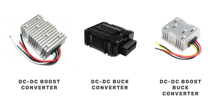
With a 10–14.4 V battery range and a regulated 12 V output, the input voltage crosses the output voltage. A buck converter may therefore lose regulation near the end of discharge, before the BMS reaches its low-voltage cutoff. A buck-boost converter covers the whole range, which makes it the match here. That conclusion applies to this input and output pair, not to every system.
Once the topology is chosen, check these datasheet items:
- Input range with margin. The range should contain the BMS cutoff, the loaded sag and any charging overshoot. In the example, something like 9–16 V.
- Continuous current at your conditions. Use the derated rating at your ambient temperature and airflow, not the 25 °C bench figure. A 5 A continuous load needs margin for thermal derating and transient demand, so verify the required rating against the manufacturer’s specifications rather than the headline current alone.
- Overload behavior. Does the current limit hold the output, or does the converter shut down and retry (hiccup mode)?
- Efficiency across the range. Read the curve at your load and at both voltage ends, not the single peak number.
- Undervoltage lockout and hysteresis. These decide when the converter switches off and back on (see Section 5).
Compare these items with the figures from your own load and pack. The only reliable test of a candidate is whether its datasheet covers your numbers.
When selecting a DC-DC converter, check that its input voltage range covers the battery’s full operating range and that its continuous output rating and overload capability can handle both normal operation and startup demands. Reviewing the specifications of products available from Power Home can help narrow down suitable candidates.
4. Account for startup loads and thermal limits
A converter with enough continuous rating can still fail at startup. Motors, pumps and radio transmitters can draw several times their running current for a short time. A peak current on the output side cannot be judged by comparing it with the continuous rating alone. The question is whether the specific converter explicitly supports that peak, for that duration, at your temperature, and what it does when the limit is reached: hold the output, fold back, or enter hiccup mode. Options include a converter with a stated peak rating, a larger continuous rating, or a soft-start on the load. Extra output capacitance can ride through a surge, but adds its own inrush at startup.
The pack side has limits as well. The input-side surge must fit inside the BMS overcurrent trip current and, just as important, its trip delay. Resistance matters too: every 10 mΩ of cell, BMS, fuse and wiring resistance costs 0.2 V at 20 A. A pack resting at 11 V can look like 10 V to the converter during the surge, which may trigger undervoltage lockout early.
Heat is the third check. Converter loss is output power × (1 ÷ efficiency − 1), and in a sealed enclosure it becomes a real temperature rise that lowers the continuous rating. Check the derating curve and the over-temperature behavior, because a converter that shuts down and restarts as it cools can cycle the equipment.
The load’s 15 A startup surge at 12 V represents 180 W for 200 ms. At 90% efficiency, delivering that peak from a 10 V battery input would require roughly 20 A from the pack, assuming the converter can sustain the output during the surge. A 60 W continuous load dissipates about 6.7 W in the converter at 90% efficiency, rising to 10.6 W at 85%. These figures help define the ratings to check; they do not establish that a particular converter will cope.
5. Check how the battery, charger, converter and BMS work together
Each part has its own protection logic, and the logic can conflict. Four interactions deserve particular attention during system integration.
Startup trips the BMS. If the surge exceeds the BMS overcurrent limit, the pack disconnects, the converter input collapses and the equipment resets. Some BMS designs stay off until a charger is connected or a reset is applied. Choose the trip current and delay above the surge, and confirm the reconnect behavior.
Low-battery shutdown chatters. If the BMS cuts off under load, the equipment dies mid-operation. Setting the converter’s undervoltage lockout above the BMS cutoff can trigger an earlier, orderly shutdown, but the threshold must be validated under the expected load and voltage sag, since one set too high shuts the equipment down prematurely. Hysteresis matters because pack voltage rebounds when the load is removed. Without enough of it, the converter restarts, the load pulls the voltage down again, and the system loops.
Charging while running. The charger sees battery current plus load current, so the taper that normally signals a full battery may never reach the termination threshold, or the charge current limit gets shared with the load. Either power the load separately from the charging path, or confirm that the charger’s termination logic is designed for load sharing.
Connecting the pack. The converter’s input capacitors charge almost instantly, which can look like a short circuit to the BMS or stress the connector. Check the BMS inrush tolerance, and use a precharge circuit or a converter with soft-start if needed.
6. Validate the design before deployment
Calculations can identify likely mismatches, but bench testing is needed to confirm performance under realistic operating conditions. These four test groups are a practical starting point; demanding environments or applications with safety and compliance requirements may need more.
- Electrical match. Reconcile on paper the pack’s lowest and highest voltage under load against the converter’s input range, the worst-case pack current against the BMS, fuse and wiring, and the charger settings against the cell datasheet.
- Peak load and temperature rise. Measure real startup current with a current probe and oscilloscope at both ends of the voltage range, with the lowest pack voltage first, where current is highest. Then run at full load at the highest expected ambient temperature until temperatures stabilize.
- Low-battery behavior. Discharge to the BMS cutoff and look for an orderly shutdown, no chatter, and a clean restart after recharging.
- Charging and recovery. Charge from empty to full, with and without the load running, and confirm termination behaves as intended. Hot-plug the pack and trigger a BMS disconnect at peak load, then confirm nothing is damaged and the system recovers. Repeat the key tests at the lowest expected temperature, including the charging limit.
What to recheck when the pack or device changes
Four points carry over to any pack or device:
- The pack’s real minimum and maximum voltage under load, and whether the equipment can take that range without a converter.
- Pack-side current at the lowest voltage, for both continuous and peak load.
- Who controls charge voltage, current, termination and temperature limits, confirmed with the battery supplier.
- Whether the BMS trip, converter lockout and hysteresis, and charger termination agree with each other.
A reliable battery-powered system depends on more than choosing components with matching headline ratings. The battery, charger, converter and load must operate within compatible voltage, current and temperature limits, including during startup and low-battery conditions. Datasheet checks narrow the options; testing under realistic operating conditions confirms whether the complete system works as intended.


