

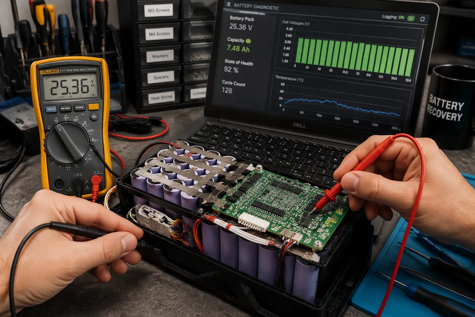
A low or zero terminal voltage does not identify the internal cell condition. It can result from shipping mode, undervoltage protection, an open connection or a hardware fault. OEMs must define diagnostics and an authorized startup decision process rather than assume the pack can be recovered.
The risks are real. An undefined wake path leads to field returns. A bypassed protection path leads to safety events. Your team is responsible for both results.
This post separates shipping mode, recoverable undervoltage, and permanent fault. It then covers battery pack wake up design, recovery tradeoffs, test acceptance, and an OEM checklist for your LiFePO4 battery programs.
Quick Answer: Distinguish intentional shipping mode from cell undervoltage and faults. Use only the manufacturer-approved wake method for the exact pack and charger combination. Low terminal voltage is not permission to force-charge, bridge protection or connect another battery.
Key Takeaways
Separate shipping mode, undervoltage and permanent faults.
Validate the supported wake interface with the actual charger and host.
Never force-charge or connect another pack for activation.
Keep DC-link precharge separate from cell recovery.
Define documented acceptance, rejection and service escalation criteria.
Part 1: Classify Pack State First
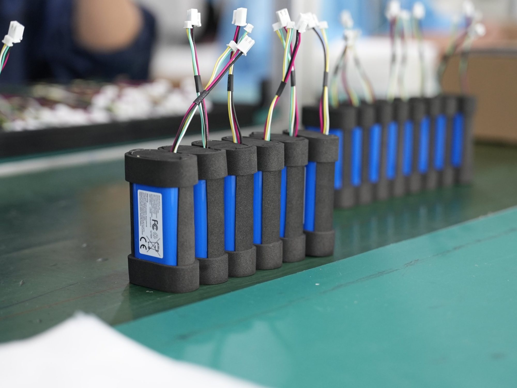
You cannot design a wake path until you know which state the pack is in. Three states look the same on a voltmeter, but each one needs a very different response. If you classify the pack wrong, you either scrap a healthy pack or ship an unsafe one.
1.1 Shipping Mode vs. Undervoltage vs. Fault
Shipping, shutdown, and deep-sleep modes turn off the discharge path on purpose. The pack lowers quiescent current so it can survive months in a warehouse or on a vessel. The cells stay charged. The output stays off. This is a protected state, not a failure.
Undervoltage protection can open the output path, but it does not prove that cells remain healthy. Residual internal drain and prolonged storage can continue to lower cell voltage. The manufacturer-approved diagnostic criteria determine whether startup is permitted or the pack must be quarantined.
A permanent fault is different. Cell damage, a failed FET, or a latched BMS protection mode after repeated trips means the pack cannot safely return to service. Only manufacturer-authorized diagnostics can tell this case apart from a recoverable one. Do not assume a deeply discharged pack is recoverable.
1.2 Diagnostic Measurements and Decision Table
Start with a documented procedure. Measure terminal and cell voltage through the authorized service interface. Read the BMS state register. Compare both readings against the thresholds your pack specification defines. Never apply a universal voltage limit from another product.
Measured condition | BMS state | Action |
|---|---|---|
Terminal voltage near zero, cell voltages above the wake threshold | Shipping or sleep mode active | Apply the defined wake stimulus |
Terminal voltage near zero, cell voltages below the wake threshold but above the fault floor | Low-voltage protection mode latched | Controlled recharge per specification |
Cell voltages below the fault floor, or cells imbalanced beyond specification | Protection latched, cell health suspect | Reject as permanent fault |
Terminal voltage present, BMS reports an active fault code | Fault latched | Reject and return for analysis |
Treat every threshold in that table as a design input. Your cell supplier’s data sheet and your own validation define the numbers. A medical device pack sitting in storage for a year and a robotics pack after long idle both follow this same logic. The classification step protects both.
Watch for one trap. A zero-volt output does not prove zero cell voltage. The BMS may have switched off the discharge path while the cells remain healthy. Confirm the state before you act.
Part 2: Battery Pack Wake Up Requirements
2.1 Quiescent Current and Storage Inputs
Every battery pack wake up design begins with four requirement inputs. First, set a quiescent current budget. This budget limits the current the pack draws while the discharge path stays off. Second, define how long the pack must last in storage, from factory shipment to first use. Third, list the transport rules that apply to your shipment mode. Fourth, name the intended wake stimulus: charger detection, a signal pin, or a service tool.
These inputs affect each other. A longer storage duration makes the quiescent current budget tighter. A stricter transport rule may force a lower state of charge at shipment. Write each input into the pack specification before you choose any circuit. Your battery management system then has a target to meet, not a guess to defend.
2.2 Wake Circuitry Design Tradeoffs
Each wake method comes with a tradeoff. Charger detection needs no extra pin, yet it depends on the charger recognizing a pack with an open discharge path. A dedicated signal pin gives you a fast, predictable battery pack wake up, but it adds a connector contact and a path for moisture or ESD. A service tool offers the most control, yet it adds a field procedure and a tool to manage.
The BMS architecture shapes this choice. Review the protection and switching topology before you commit. A well-designed under-voltage lockout releases only through the approved stimulus. That behavior keeps the protection intact during storage and transport.
Chemistry changes the inputs, not the method. A LiFePO4 battery pack, an NMC pack, and an LCO pack all need a defined stimulus to wake the battery. Set the thresholds from your cell supplier data and your own validation. Never copy a limit from another product.
Part 3: Engineering an Authorized Wake Interface

3.1 Charger-Based and Signal-Based Wake
Charger detection and a dedicated wake signal are possible architecture choices, not universally approved methods. Verify which functions the selected BMS supports and validate them with the actual charger, host, connectors and firmware.
Charger-based wake requires coordinated pack and charger design. A generic lithium setting or advertised 0 V activation feature is not evidence of compatibility. Document the allowed detection stimulus, cell eligibility checks, current and temperature limits, timeout, and response to an invalid pack. Never use a recovery charger to override a rejected battery.
A signal-based wake interface must specify its powered detection circuit, input limits and false-trigger behavior. The following vehicle-oriented examples are architecture-specific, not pinout instructions for a portable pack.
Wake-Up Signal | Trigger Source | How It Works |
|---|---|---|
Level, edge, or resistance | Internal or external signal | A voltage level, edge transition, or specific resistance turns on the power management chip or MCU |
KL15 ignition | Vehicle ignition switch | The switch closes and sends +12V to the BMS controller |
VCU hardwire | Vehicle control unit | The VCU wakes first, then sends a hardwired signal to the BMS |
AC charging PP | Resistance on the PP pin | The specified resistance confirms charger connection and wakes the BMS |
CAN bus | Bus traffic monitoring | The transceiver detects a wake message and turns on the MCU |
Measure sleep current, wake latency and false-wake immunity on the actual assembly. Derive debounce, signal filtering and startup timeouts from the host requirements and circuit behavior; there is no universal timing or current limit for all packs.
3.2 Recovery Eligibility and Protection Boundaries
A 0 V reading at the terminals does not mean the cells sit at 0 V. The BMS may have switched off the discharge path while cell voltage remains higher. Only manufacturer-authorized diagnostics can tell whether a deeply discharged LiFePO4 battery can be recovered. Your design must send that decision to the manufacturer, not to the field technician.
This is why a controlled wake-up path matters more than any repair trick. Build the stimulus into the pack architecture. Validate it during design. Then let authorized service apply it.
Never bypass protection, connect another battery for activation, or force-charge an unresponsive pack. Quarantine damaged or disqualified batteries under the manufacturer service procedure.
If the pack does not respond to its approved wake stimulus, stop and escalate to authorized service. Do not repeat activation attempts or improvise a power source.
Part 4: Startup Across 12V, 24V, and 48V Systems
4.1 Voltage-Specific Wake and Precharge
Nominal 12 V, 24 V and 48 V labels do not define wake or recovery thresholds. Specify series count, chemistry, individual cell limits, BMS hysteresis and host input range. Any numeric thresholds shown in the accompanying illustration are illustrative only and must not be used as design or service limits.
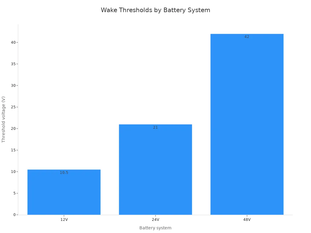
DC-link precharge limits inrush into a capacitive host load; it is not recovery charging of undervoltage cells. Size the resistor, switching path and timeout from bus capacitance, voltage difference, pulse energy and component ratings. Verify bus voltage before closing the main path and stop startup if the expected response is absent.
4.2 Multi-Pack and Parallel String Startup
Parallel packs require a manufacturer-approved architecture with controlled connection, reverse-current behavior and fault isolation. Startup order alone cannot prevent cross-current between unequal terminal voltages. Validate current sharing, one-pack disconnect and load transfer without directly connecting packs to equalize them.
Part 5: When the Charger Won’t Recognize 0V
5.1 Controlled Recharge and Balancing
A charger may reject a pack because of voltage detection, authentication, temperature limits, an interface fault or a BMS lockout. Diagnose the documented state through authorized interfaces; do not assume that applying voltage will resolve it.
Before any charging is permitted, authorized diagnostics must establish cell eligibility and absence of damage or disqualifying faults. The following checklist replaces field recovery shortcuts. It is not an instruction to revive a deeply discharged pack.
Procedure | Method | Key parameters |
|---|---|---|
Diagnostic eligibility | Do not connect another battery. Use manufacturer-authorized diagnostics to determine whether startup is permitted. | No universal activation time or voltage |
Approved charger and pack pairing | Use only the exact charger and sequence qualified by the pack manufacturer | Apply documented timeout and abort criteria |
Verification | Re-measure terminal voltage | Escalate if voltage stays at 0V or drops back |
Use only the exact charger and procedure approved for the pack. A low-current setting, fixed waiting time or balancing cycle does not make damaged cells safe. Define abort criteria and service escalation; do not repeat activation attempts on an unresponsive pack.
5.2 Return-to-Service Acceptance Criteria
Set acceptance criteria before any pack reenters service. Check cell balance against your specification. Make sure the BMS reports no latched fault. Run one full cycle and compare capacity to your design target. A weak or imbalanced cell fails these checks, and you reject that pack.
Never use a car battery, a jump pack, a mismatched voltage source, or an unregulated supply. Never connect directly to bare cells.
A deeply discharged LiFePO4 battery that fails authorized diagnostics is a permanent fault. Replace it. This 0v recovery guide covers service procedure only, not cell repair. Apply the same rule to a medical device pack and a robotics pack: escalate, do not improvise. Write the battery pack wake up steps in your field-service procedure so every technician follows the same path after deep discharge.
Part 6: Test Acceptance and OEM Checklist
6.1 Validation Tests for Wake and Fault Rejection
Put three validation tests into your design verification plan. Each test proves one behavior that your field team depends on.
Validate startup from each intended shipping and sleep state at the specified SOC and temperature limits. Record wake signal, BMS status, host reset behavior and any precharge sequence. Apply isolation monitoring and contactor checks where required by the actual system architecture, not as universal requirements for every portable pack.
Validate undervoltage lockout and authorized recovery eligibility using controlled test equipment and manufacturer-approved procedures. Use a simulator where appropriate for fault-state verification. Do not create damaged cells or force-charge over-discharged packs as an ordinary acceptance test.
Verify fault rejection using safe simulated inputs or a dedicated laboratory test plan. Confirm that invalid cell voltage, sensor faults and latched protection states block startup as specified, and that the host receives the correct status.
6.2 OEM Production and Field-Service Checklist
Turn the requirements into a checklist that your production and service teams sign off on.
Area | Checkpoint |
|---|---|
Requirement definition | Quiescent current budget, storage duration, transport rules, and wake stimulus written in the pack specification |
Wake-path validation | Shipping-mode startup, authorized eligibility checks and fault rejection validated on the released design |
Labeling | Approved wake method, compatible charger identification and service escalation instructions |
Field service | Escalation rule for unresponsive packs written into the service procedure |
Review this checklist at each design review. Update it whenever the cell, the protection topology, or the charger changes.
Reliable startup comes from two habits. You sort the pack state the right way, and you set up a battery pack wake up path that respects protection. Shortcuts seem quicker, but they push the risk out into the field.
Never bypass protection or attempt to revive damaged cells. Recovery eligibility is a manufacturer-defined decision, not a chemistry-wide assumption.
Now turn these requirements, tradeoffs, and acceptance criteria into your own pack specification and OEM checklist. Write the wake stimulus, the bms state checks, and the rejection rule into both documents. Your production and service teams then follow one clear path.
FAQ
Is a pack that reads zero volts always dead?
No. The BMS may have turned off the discharge path while the cells still hold charge. A zero-volt reading at the terminals only tells you the output is off. Check the state with authorized diagnostics before you decide anything.
What is the approved way to wake up a lifepo4 battery?
Use the stimulus your pack specification defines. That means a charger with a recovery function or a dedicated signal path. Both release the protection latch through an approved route. Never force current into the terminals to skip the process.
Why won’t my charger recognize a pack at zero volts?
Possible causes include an open BMS output, detection thresholds, authentication or a fault. Confirm the exact pack and charger requirements with the manufacturer. A generic lithium charger with a recovery feature is not automatically compatible.
Can one pack in a parallel string trip another during startup?
Yes. Disconnecting or enabling one pack can transfer load or create cross-current. Validate coordinated startup, allowed voltage differences and reverse-current isolation in an approved multi-pack architecture; a staggered sequence alone is insufficient.
When should a pack be rejected instead of recovered?
Reject any pack that fails cell-health checks or shows a latched fault after authorized diagnostics. A lifepo4 battery pack with weak or imbalanced cells is a permanent fault. Replace it. Recovery applies only to packs that pass the defined checks.


