

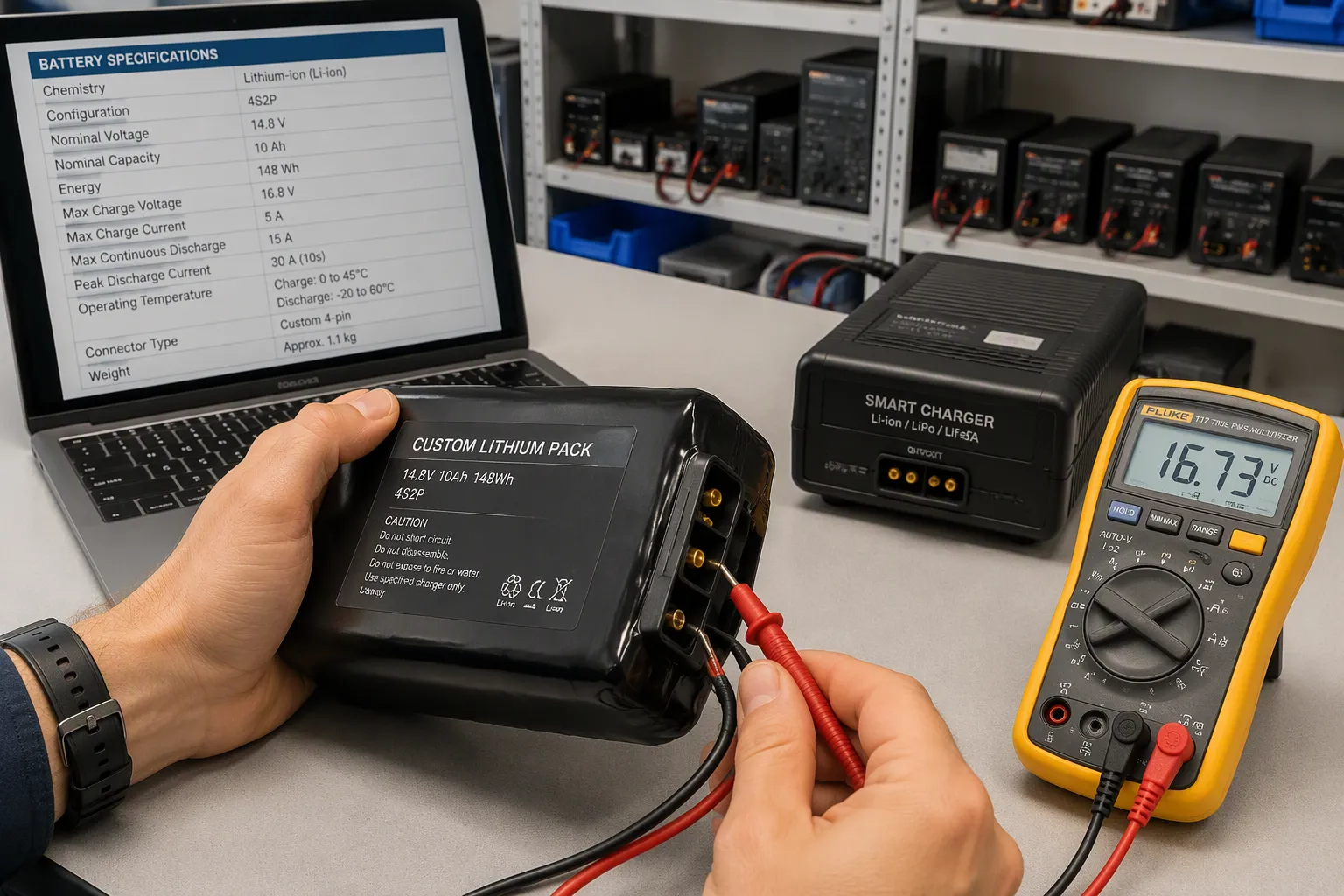
Quick Answer: True battery charger compatibility means matching the full lithium charging profile, termination method, temperature limits, communication and wake-up behavior, and host power-path interaction. Voltage and connector matching are necessary but not enough.
A charger that fits physically can still overcharge, undercharge, fail to wake a protected pack, or conflict with the host power path. For OEM/ODM teams, that gap creates real engineering and procurement risk. You may pass incoming inspection and still ship a battery pack that acts in ways you cannot predict in the field.
This post gives you requirement definition, design tradeoffs, test acceptance, and an OEM checklist for custom battery pack programs. You will learn how to qualify a battery charger against a lithium battery specification. You will also learn how to document safety decisions your quality team can defend.
Key Takeaways
Match charger voltage, current and algorithm to the exact battery pack, not only connector fit.
Set temperature inhibit and recovery from the approved cell and pack specification.
Verify wake signals and communication only where the architecture requires them.
Validate charge termination and input-power sharing while the host is operating.
Retain test evidence, configuration and change-control records before release.
Part 1: Battery Charger Compatibility Basics
1.1 Voltage, Connector, and Interface Match
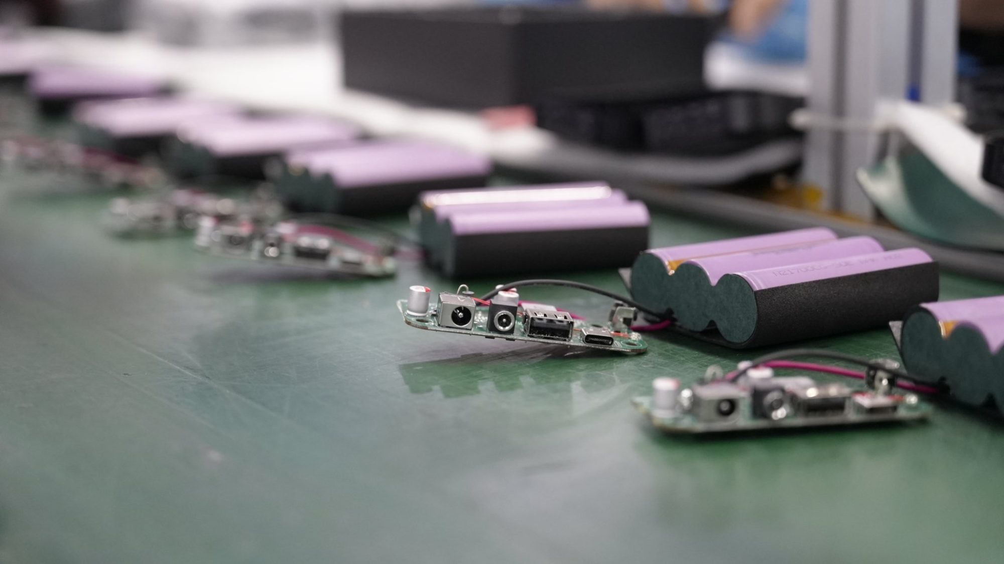
Battery charger compatibility starts with the whole system, not just the plug. A replacement or specified battery charger must cover the host device’s full voltage range, charging circuit, load profile, mechanical envelope, and battery interface. The connector is only the entry point. Think of the charger, pack, and host as one electrical system.
Confirm the exact charge-voltage limit, current profile and regulation tolerance for the selected cell model and series count. The table is an arithmetic example for cells specified at 3.7 V nominal and 4.20 V maximum; it is not applicable to every lithium chemistry. Pack-level approval must also address imbalance, temperature, charger overshoot and protection coordination.
Battery Configuration | Nominal Voltage | Maximum Charge Voltage (at 4.20V/cell) |
|---|---|---|
1S | 3.7V | 4.20V |
2S | 7.4V | 8.40V |
3S | 11.1V | 12.60V |
4S | 14.8V | 16.80V |
5S | 18.5V | 21.00V |
6S | 22.2V | 25.20V |
7S | 25.9V | 29.40V |
8S | 29.6V | 33.60V |
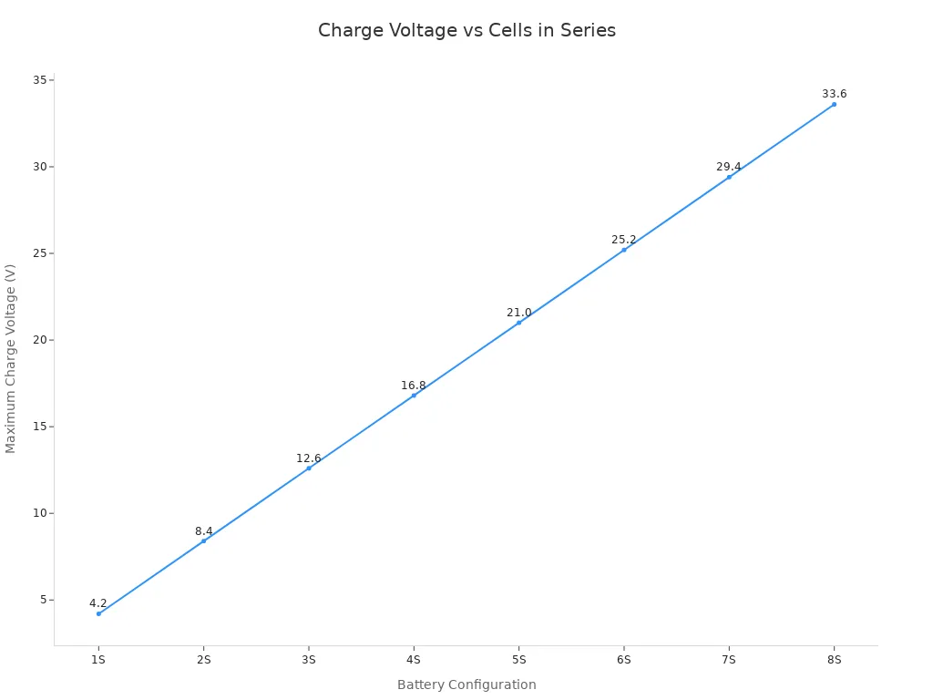
A 22.2 V nominal pack in a 6S configuration with cells rated for 4.20 V maximum needs about 25.2 V at full charge. Imagine a 48 V charger hooked to a 36 V pack. It pushes voltage far above the pack’s full-charge level. Cells overcharge, and the BMS must step in or fail. That is the mismatch result you want to avoid.
Compare the charger’s maximum output current with the pack’s stated charge current limit. A charger rated above that limit can stress cells even when voltage looks correct. Universal chargers with adjustable contacts can match terminal spacing. Contact spacing alone does not promise electrical compatibility. Check polarity, voltage, current, and communication before you trust the fit. Safety depends on that check.
1.2 Chemistry and Pack Configuration Match
Battery chemistry and pack configuration must match the charger’s algorithm. Every lithium battery pack needs a profile suited to its cells. LiFePO4, NMC, LCO, and LMO all need a lithium-appropriate algorithm, yet their cell-level nominal voltages and limits differ. As an editorial reference at cell level, LiFePO4 sits near 3.2 V nominal, while NMC and LCO sit around 3.6 to 3.7 V. These cell-level ranges depend on test conditions and are not guaranteed pack specifications.
Pack configuration adds a second layer. Series count sets charging voltage. Parallel count sets capacity and how current divides. Your charge current must respect the assembled pack’s specification, not just a single cell datasheet. A generic lithium setting on a multi-chemistry charger is not proof of suitability. Verify the algorithm against the cell manufacturer’s datasheet for the exact model you buy.
Charger compatibility also depends on documented battery matching requirements. Confirm the cell chemistry and model, nominal voltage, maximum charge voltage, recommended charging current, termination current, temperature range, series and parallel layout, BMS protection, operating conditions, and certification needs. Record the configuration so purchasing orders against a defined part, not a verbal description.
Part 2: Lithium Charging Profile and Termination
2.1 Charging Current and Voltage Limits
Normal charging follows a set lithium charging profile. Fault protection is a separate layer. Your pack datasheet defines the charge-current limits and the top charging voltage. The charger must follow those numbers, not a generic default. A typical lithium-ion profile runs a constant-current stage up to a termination voltage. Then it runs a constant-voltage stage until current drops to a cut-off point.
Charging Stage | Parameter | Specification basis |
|---|---|---|
Constant-Current (CC) | Termination voltage (max voltage) | Exact cell and series-count limit |
Constant-Voltage (CV) | Cut-off current | Approved termination threshold |
Treat these as typical values, not universal limits. Your battery chemistry and cell count set the real charge voltage. A 4S NMC pack needs a different top charging voltage than a LiFePO4 pack with the same series count. Confirm the charging voltage against the cell manufacturer’s datasheet for the exact model.
Set charge current from the exact cell and pack limits, charger capability, temperature and thermal path. Higher current can increase heating and lithium-plating risk under unfavorable conditions. Adaptive control requires validation; one experimental result is not a universal performance promise.
2.2 Termination Methods and Tradeoffs
For a specified CC-CV profile, the voltage limit governs transition into CV and the documented battery-current threshold and other conditions govern completion. Safety timers provide an additional limit, not an interchangeable charging algorithm. BMS overvoltage cutoff is a fault response, not the routine completion method.
Aging can change capacity, impedance and charge behavior, but does not make every charge stage longer. Define replacement from runtime, condition, faults and the approved service policy, not a universal capacity percentage. Any cell-level repair requires an authorized, qualified process.
Part 3: Temperature Limits and Fault Protection
3.1 Normal Charging Versus Fault Protection
Normal charging follows the profile your pack datasheet defines. Fault protection is a separate layer. It kicks in when something goes wrong, like overvoltage, overcurrent, or too much heat. Keep these two layers apart in your requirements. A charger that charges correctly in normal conditions may still lack the protection your pack needs.
Protection may be distributed between pack, host and charger. A charger does not automatically replace protection during discharge, storage or disconnected use. Document the location of each required function and validate its response.
Verify the actual voltage, current and temperature coverage, thresholds, delays, recovery and diagnostic reporting. BMS and PCM requirements depend on the design, not the label alone.
3.2 Temperature Windows and Recovery Behavior
Temperature windows come from the pack specification, not from habit. The table shows common lithium-ion charging ranges as an editorial reference. Check the real window against your cell manufacturer’s datasheet.
Condition | Charging Temperature Window |
|---|---|
Permitted charge envelope | Model-specific limits |
Current derating | Approved temperature-current profile |
Manufacturer-recommended minimum for cycle life | Defined by qualified cell data |
Charging outside the exact cell-approved temperature and current envelope may cause degradation or unsafe conditions. Follow model-specific limits and any required derating. Specify sensor location and tolerance, charge inhibit, hysteresis and recovery. Validate disconnected or shorted sensors. Do not bypass protection to charge a cold or faulted pack.
Part 4: Communication, Wake-Up, and Power Path
4.1 Handshake and Wake-Up Behavior
Some packs need a documented wake signal after shipping mode or a recoverable event; others charge without digital communication. A switched-off output must be distinguished from dangerously low cell voltage or permanent failure. Do not force current or bypass protection. The following are product-specific validation checkpoints, not a universal EV-style handshake.
Verify the approved pack model, pinout, polarity and charge profile before enabling current.
Test the defined wake path if required; reject permanent faults and unsafe cell conditions.
Check temperature and identification inputs where used, including disconnected or invalid signals.
Verify protocol, timing and loss-of-link behavior only if digital communication is required.
Confirm startup, current and voltage regulation, normal termination and permitted recovery against approved limits.
Specify supported analog or digital signals, electrical limits and timing in the integration drawing. Define the response to an unsupported pack, missing signal or failed wake attempt. Thermistor and cell-sense leads are needed only if the approved architecture uses them; a smart-charger label does not establish cell-monitoring coverage.
4.2 Host Power-Path and Charging While Operating
Charging during operation requires a defined power budget. If input power is insufficient for system load and charging, the architecture must reduce charging, limit the load or enter an approved mode. Check actual current paths and input limits rather than assuming every charger supports load sharing.
Tradeoff option | Design implication |
|---|---|
Reduce charge current | Lowers charging rate so the shared input budget covers the system load |
Limit system load | Constrains device operation to stay within available input power |
Define a controlled operating mode | Manages device state so charging and operation coexist within limits |
Each option carries consequences for heat, charge time, and safety. A medical cart that charges during rounds, a security camera on standby power, and a robotics platform topping up between tasks all face the same question: how much load can share the input?
Test idle, normal and peak host loads during charging, input removal and reconnection, protection interruption and permitted recovery. Distinguish adapter current, system-load current and actual battery charge current. A load across the battery can interfere with current-based termination in some architectures. TI’s power-path charger documentation illustrates one design that manages the system load separately; this is not a universal charger specification.
Part 5: Charger Compatibility for Retrofits
5.1 Test Acceptance for Changed Packs
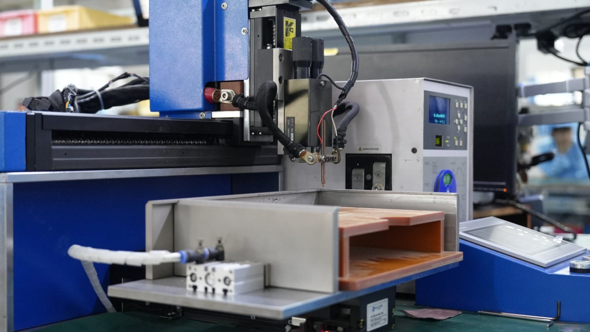
A retrofit changes the system, so you must test it again. Start by gathering the original pack drawing, cell data, charger spec, pinout, and firmware requirements. Measure host standby, normal, startup, and peak loads, including returned energy. Then define the allowed voltage, dimensions, weight, usable runtime, and temperature conditions. Identify exactly what changes: cells, protection, housing, connector, charger, firmware, or indication logic. Agree on revalidation scope, sample acceptance, and approval owners before installation.
Physical fit does not prove charger compatibility. A mating connector may still carry wrong polarity, a different thermistor, or missing data signals. A fitting enclosure may restrain pouch expansion or leave inadequate insulation. A stronger protection board cannot fix an incompatible charger. Keep the existing charger only when its voltage, current, charging profile, temperature controls, and restart behavior clearly match the exact replacement. A higher-capacity pack forces you to recheck charging duration, timeouts, mass, thermal behavior, runtime indication, and stored fault energy. Transport test summaries such as UN 38.3 cover shipment only. They do not prove device-level retrofit approval.
Acceptance criteria to verify | |
|---|---|
Electrical interface | Pinout, polarity, voltage window, startup and load transients |
Charging | Current, voltage, completion, restart, temperature response, charging during use |
Protection coordination | Defined fault responses, host shutdown, fuse coordination, recovery |
Mechanical and thermal | Fit, retention, strain relief, contact heating, enclosure temperatures |
Device function | Runtime, alarms, data preservation, essential operating functions |
Smart interface | Communication, identification, fuel-gauge behavior, loss-of-link handling |
Test with representative operating profiles, temperatures, and battery states. Include aged-battery conditions when you claim lifetime performance. Recheck EMC and measurement quality whenever converters, cables, or electronics change. Hazardous fault tests require qualified personnel and proper facilities.
5.2 Safety Documentation and Traceability
Retain the pack and charger specifications, interface drawings, relevant reports, released software or parameters, and test records. Determine applicable battery, charger and host-device requirements by intended use and destination market. IEC 62619, UL 2054 and UN 38.3 have different scopes and are not a mandatory universal checklist for every product. Match each claim to the actual model and evidence.
Category | Required evidence |
|---|---|
Product specification | Battery spec, cell datasheet, pack drawing, BMS/PCM spec, connector and cable drawings |
Charging and testing | Charging requirements, testing requirements, inspection standards |
Quality records | Test report, certificate or declaration, approved sample reference |
Change control | Change-control procedure in purchase or quality documentation |
Traceability | Batch records traced from cell receipt to finished packs |
Corrective action | Failure mode, root cause, containment, permanent fix, verification |
Compare quotations against the same scope: sample qualification, documents, inspection, engineering support, traceability and change notification. Price alone does not establish quality or compliance. Resolve exclusions before approving the combination.
Part 6: Battery Charger Specification and Installation
6.1 Writing Requirements from Pack Data
Build the charger specification from the pack datasheet, not from a catalog. Start with the system voltage range and cell count. Next, write down the allowed charging voltage window and charge-current limits at the real operating temperature. Add the allowed charging temperature range, then the communication needs: handshake, wake-up, and communication protocol. Write each value with its source document.
Cell performance is not pack performance. A cell datasheet gives cell-level limits under test conditions. The assembled custom battery pack adds a BMS, wiring, and thermal mass, so its approved profile governs the battery charger. System validation then proves the charger, pack, and host work together. Keep these three layers separate in your charging requirements.
6.2 Controlled Installation and OEM Checklist
Follow a fixed sequence at installation:
Confirm charge voltage, current, completion and restart against the approved pack profile. Do not copy lead-acid boost, float or equalization settings, and do not use BMS fault thresholds as normal charger targets.
Turn off incompatible lead-acid functions such as equalization and desulfation unless the manufacturer approves them.
Confirm which device enforces low-temperature charging protection, and set inhibit and recovery behavior to the maker’s requirements.
Set up BMS-to-controller communication where closed-loop control is required, and test safe recovery after a BMS interrupt.
Watch an initial charge, then complete a commissioning record covering models, firmware, limits, and recovery responses.
Sign-off area
What to confirm
Engineering
Charging voltage, charge current, temperature limits, communication compatibility, charger configuration
Purchasing
Approved charger part, firmware version, change control
Quality
Commissioning record, test acceptance, traceability
Good charger compatibility and configuration depend on documented safety decisions at every stage.
Part 7: Common Pitfalls to Avoid
7.1 Electrical and Thermal Pitfalls
Voltage mismatch is the biggest problem. A charger made for one series count sends the wrong top voltage to another pack. This causes permanent chemical damage to the cells. Matching only by contact spacing hides this risk, because a universal charger can touch the terminals and still deliver the wrong profile. Before you approve any charger, check chemistry, series cell count, rated capacity, charge voltage limit, and discharge current limit against the cell manufacturer’s data.
When cells, charger, enclosure, firmware or thermal conditions change, reassess the affected charging requirements. Check sensor placement, ambient extremes and local hot spots against approved limits. Do not impose an arbitrary universal temperature limit or degradation timeline.
7.2 System-Level and Documentation Pitfalls
Document the division of responsibilities among charger, pack and host, including required pins, thermistor characteristics and fault responses. Retain the original configuration, changes and revalidation decision for a retrofit.
Not every BMS requires a digital charger link. Local monitoring and balancing may operate independently. If closed-loop charging is specified, validate protocol, scaling, limits, timeouts and fallback. Communication loss must produce the approved response, not an assumed universal shutdown.
Charger compatibility is a system property. Match the charging profile, thermal limits, termination and any required wake or power-path behavior to the exact pack and host.
Use a short decision framework. Engineers confirm the charging profile and bms behavior against the pack data. Purchasing verifies the approved part, firmware, and change control. Quality signs off on test acceptance and traceability. Each team checks its own layer before release.
Written requirements and recorded test acceptance are still your lasting safeguard. Write the lithium battery specification down, test against it, and keep the record with the unit. That record protects you long after the shipment leaves.
FAQ
Can I use a charger that fits the connector but isn’t the original?
A non-original charger may be acceptable after qualification against the exact pack and host requirements. Confirm polarity, regulation, algorithm, temperature controls, termination and any required wake or communication behavior. Obtain the relevant manufacturer or OEM approval before service use.
How does the BMS affect charger selection?
The BMS or PCM provides the protective functions actually implemented. The charger normally regulates charging and handles completion. Verify coordination during interruption and recovery. Communication and extra sense lines are required only if specified by the approved architecture.
What changes when an aging pack is replaced?
Review the replacement model, cell limits, protection, charger settings and host interface. Aging does not imply every charging stage takes longer. Set revalidation scope from the change and test completion, temperature and runtime under representative conditions.
Which documents should be retained for charger qualification?
Keep the pack specification, charger datasheet, test reports, and change-control records. Being able to trace from cell receipt to finished pack matters. Your quality team needs these records to defend safety decisions. Without them, you cannot prove the charger and pack work together as a system.


