

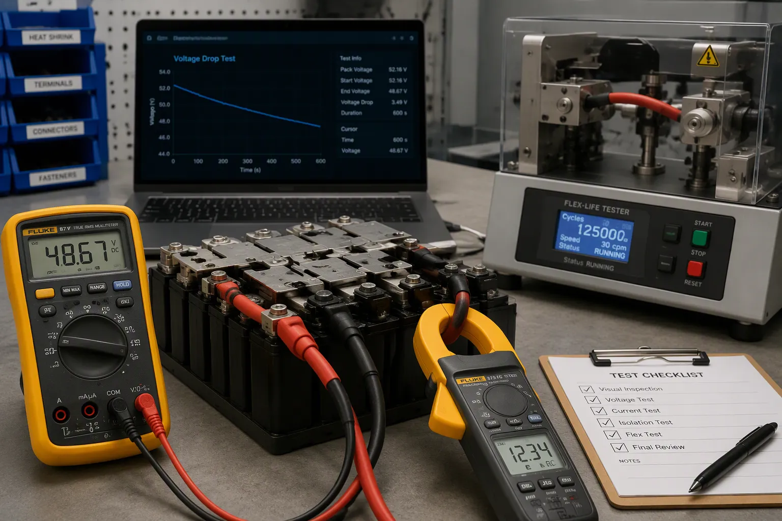
Every battery pack wiring choice pulls you in three directions. The wire must carry current without getting too hot. It must deliver voltage within load tolerance. And it must survive motion during installation. No single table settles these choices. Gauge, length, insulation, termination, and routing work together as a system. You confirm them by test, not by guesswork.
Think of this as a repeatable sequence. You define requirements first, then size the battery cable for current with derating. Next, you check voltage drop at peak load. Finally, you validate flex-life through physical testing. Each step builds on the last. This approach turns a complex decision into a manageable process for custom lithium packs.
Key Takeaways
Before you pick a wire gauge, figure out your current needs, temperature range, and routing path.
Start with a wire size chart, then change it for bundling, heat, and connector limits.
Check the voltage drop at peak current across the full round-trip cable length. This makes sure the load gets enough voltage.
Test how long the cable lasts by bending it at the radius used in the installation and checking for damage.
Check the connectors and strain relief to stop failures. Connectors often limit performance more than the wire itself does.
Part 1: Define Requirements for Battery Pack Wiring
Quick Answer: Start by writing down your requirements. Record the continuous and peak current profile, the ambient temperature range, the routing path and its motion, and the connector envelope. Every choice you make later — gauge, insulation, termination — comes back to these inputs.
1.1 Current Profile and Ambient Conditions
Specify continuous current, startup and stall pulses, duration, repetition and current paths. Record local ambient temperature and allowable conductor and terminal temperatures. The table below is a requirements template, not a chemistry-based cable rating.
Load input | Required definition | Validation condition |
|---|---|---|
Continuous load | Measured sustained current | Actual local temperature range |
Transient load | Peak, duration and repetition | Minimum loaded pack voltage |
Storage and startup | Quiescent drain and inrush | Specified environment and duty cycle |
Use measured battery-side current in the assembled device. A cell discharge rating does not establish the allowable current of a cable, connector, termination or sealed pack.
1.2 Routing, Motion, and Interface Envelope
Next, sketch out the physical path. Measure cable length along the real route, not the straight-line distance. Note every bend, every pass-through, and every point where the battery cable flexes. A fixed infrastructure cabinet allows a stiff conductor. A security camera pan-tilt assembly or a surgical robot arm needs a flexible one.
Define the interface envelope early. Connector body size, terminal spacing, and mating clearance limit gauge before any ampacity table matters. Record the system voltage and the maximum load current the load will ever demand. Capture the amperage load at each branch, too. These numbers feed the voltage drop check later. Get the OEM to sign off on this requirement set before sizing begins.
Part 2: Current Rating and Battery Cable Size Chart
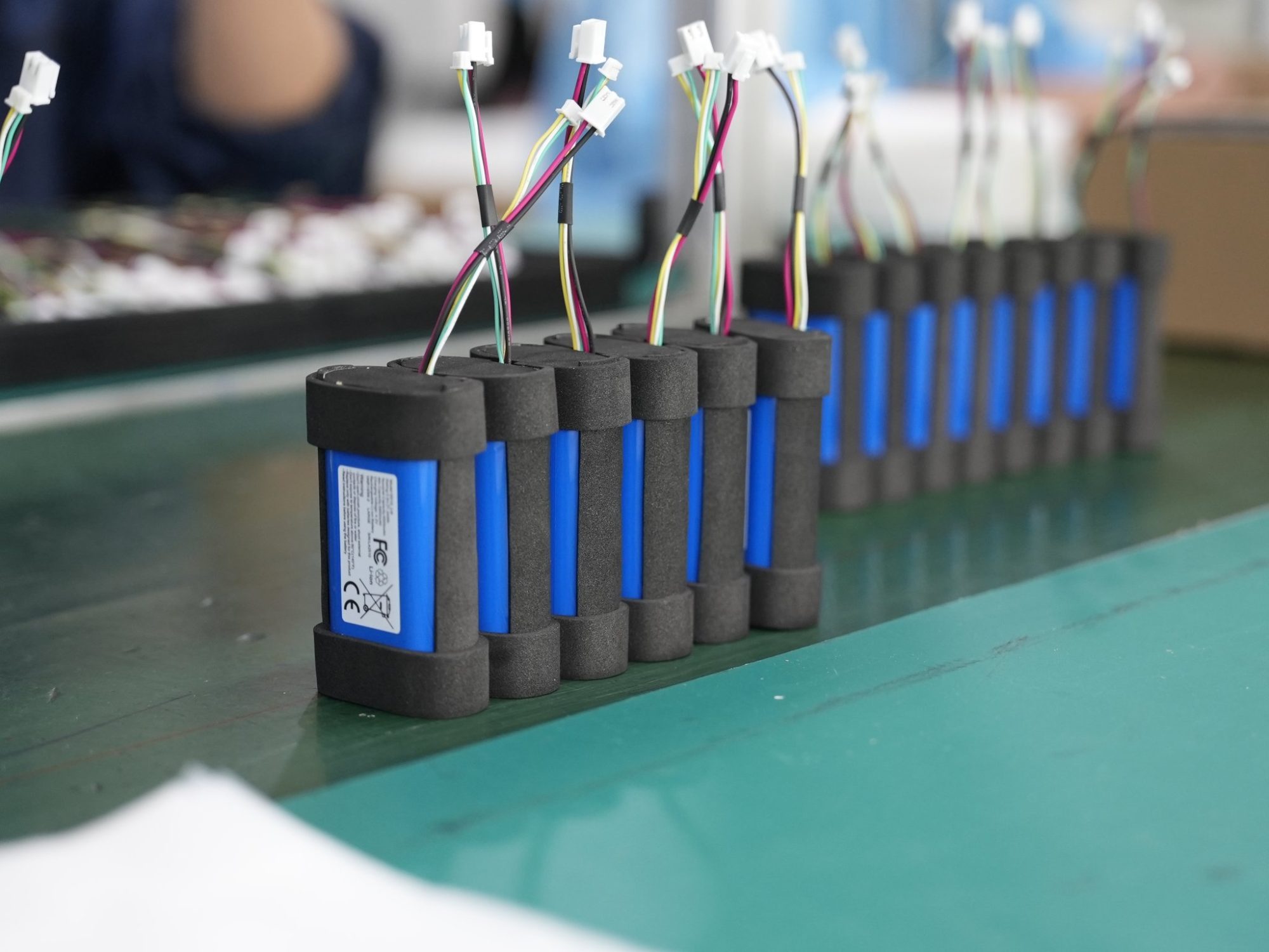
Separate ampacity tables from voltage-drop charts. Ampacity depends on conductor construction, insulation, ambient temperature and installation conditions; it is not selected from nominal pack voltage alone. Voltage-drop charts additionally depend on current and route length. Confirm the units, whether length is one-way or round-trip, and the stated temperature before using any chart. Verify insulation and connector voltage ratings against maximum pack voltage and relevant transients, then validate thermal rise and loaded host voltage in the installed assembly.
Check steady thermal loading and transient voltage drop separately. Repetitive pulse heating depends on the full current waveform, not only its peak. Coordinate fuse behavior with the conductor and connector damage limits, BMS response and fault current; a fixed 1.25 multiplier is not a universal selection rule.
2.1 Ampacity, Bundling, and Temperature Derating
Read the conditions of the specific ampacity table: conductor construction, installation method, ambient, insulation rating and loaded-conductor count. Tables do not all assume free air. Apply the relevant derating method and verify hotspot temperatures in the actual bundled harness and enclosure.
2.2 Connector and Terminal Selection Derating
Connector and terminal selection often sets the real limit. A derating curve is not a safety margin but a thermal operating limit describing the maximum permissible current under strictly defined boundary conditions; the connector must always be treated as part of a thermo-electrical system alongside cables, crimps, PCB, and installation environment.
Factor | Effect on derating |
|---|---|
Contact resistance | Determines I²R losses and heating; depends on geometry, contact force, plating, surface quality, aging/corrosion |
Housing material | Sets maximum continuous operating temperature and influences heat dissipation |
Number of loaded contacts | More energized pins heat each other via thermal coupling, reaching the thermal limit sooner |
Installation/cooling | Free convection vs. sealed enclosure vs. forced airflow strongly changes permissible current |
Connected conductor (wire cross-section) | Thicker copper acts as a heat sink drawing heat from the contact; thin wires create thermal bottlenecks |
Termination quality (crimp) | Poor crimps raise resistance, create hot spots, and lower permissible current below datasheet values |
Use the selected connector manufacturer derating data under matching wire, contact and cooling conditions. A square-root temperature estimate is only a preliminary model, not a validated rating. Do not multiply single-contact current by pin count or assume equal sharing among parallel contacts.
Part 3: Voltage Drop in Battery Cable Selection
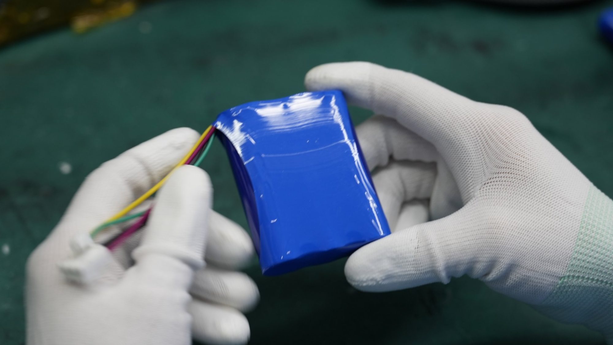
A battery cable that passes the ampacity check can still fail the load. Resistance along the conductor turns part of the system voltage into heat. The load then sees less than the pack delivers. You must check voltage drop at peak current, not average current.
3.1 Calculating Drop from Length, Gauge, and Current
For equal outgoing and return conductors, V_drop = 2 x I x r x L, where r is resistance per unit length at operating temperature and L is one-way length. Alternatively use I x r x total round-trip length; do not double that length again. Add connector, crimp, fuse, switch and interconnect losses separately.
Multiply the drop by the current and you get the power lost in the wire. That number matters twice. It steals efficiency from the pack, and it adds heat inside an enclosure that already traps heat.
Set allowable voltage drop from the host input range and minimum loaded pack voltage. The percentages in the following table are generic discussion examples, not custom-pack acceptance limits.
Circuit Type | Typical Limit | Rationale |
|---|---|---|
General branch circuits | 3% | Balances efficiency against conductor cost |
Combined feeder plus branch | 5% | Keeps total system loss practical |
Sensitive electronics | 1–2% | Preserves signal integrity and startup margin |
Use a calculation worksheet that records conductor temperature, full current path and contact losses. Validate the result with voltage measurements at the actual host terminals during worst-case pulses and sustained operation.
3.2 Tradeoffs: Gauge, Length, and Architecture
Wire gauge selection trades cost against loss. Each step up in conductor size buys a smaller gain. The table below is a hypothetical example of that curve:
Wire Gauge | Relative Cost per ft | Voltage Drop | Incremental Gain |
|---|---|---|---|
10 AWG | 1.0x | 4.5% | — |
8 AWG | 1.5x | 2.8% | 1.7% |
6 AWG | 2.2x | 1.8% | 1.0% |
4 AWG | 3.5x | 1.1% | 0.7% |
2 AWG | 5.5x | 0.7% | 0.4% |
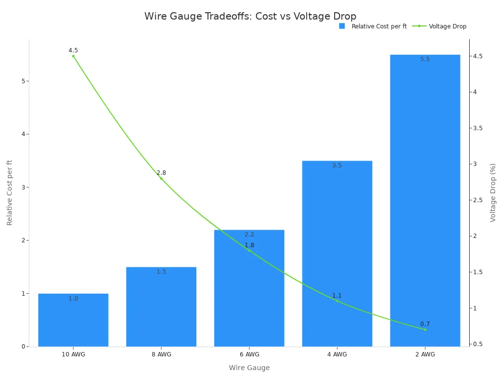
Large-gauge copper cables are expensive and stiff. Doubling wiring cost for a tiny efficiency gain is rarely a good idea.
Shortening the cable length often works better than upsizing. Move the pack closer to the load, or split the run into a short feeder and a local branch. In a surgical robot arm or a security camera gimbal, a shorter flexible run also cuts the mass that the joint must move. Check the allowable voltage drop against your load amperage and maximum current before you commit to an architecture.
Part 4: Flex-Life Validation and Bend Radius
4.1 Stranding, Insulation, and Bend Radius Rules
Stranding class decides how a battery cable acts when it moves. Coarse stranding handles tight bends poorly and wears out fast. Fine stranding spreads the strain across many small wires. Common flexible classes include:
Class G, Class H, and Class I
Type DLO (Diesel Locomotive)
Class 5 metric (mm²), also called “f”
Class K (machine tool wire and welding cable)
Product names can fool you. A cable sold as “battery cable” or “welding cable” does not promise a stranding class. Check the class before you mount the wire.
Rope lay twists stranded groups together in rings. It gives the most flexibility in larger sizes and fits welding cable, mining cable, and heavy-duty portable cables that must flex while carrying high current.
Specify insulation voltage and temperature ratings, abrasion resistance, cleaning-fluid compatibility and flame requirements for the application. Obtain static and dynamic bend-radius limits for the exact cable. Do not assume welding or marine cable is qualified for repeated robotic motion.
4.2 Flex Test Setup and Acceptance Criteria
Build the test around the real installation. Mount a sample at the routing bend radius, apply the working current, and cycle it through the motion range the joint sees. Track conductor resistance and check insulation for cracks. Acceptance criteria belong to the application, so agree on them with the OEM before testing starts. Do not borrow limits from another program.
Fine stranding alone does not qualify a cable for repeated motion. Define bending versus torsion, travel, speed, acceleration, bend radius, temperature, working current and cycle count for the actual duty. Monitor intermittent continuity during movement as well as resistance drift and insulation damage at inspection intervals. Include production-intent clamps, connector exits and strain relief, and confirm electrical and thermal performance after testing. Agree on sample count and acceptance limits before validation.
Part 5: Integrate Current, Drop, and Flex-Life
5.1 Application Scenarios for Custom Packs
Each application puts stress on a different limit. A surgical robot arm needs a flexible battery cable that lasts through thousands of joint cycles. A security camera gimbal needs a short run with low voltage drop at peak pan current. An industrial skid needs a heavy conductor sized for surge. A medical cart needs a small connector space. A telecom cabinet needs a long feeder with a tight drop budget.
You solve these cases the same way. Start with the battery cable size chart to make a short list of gauges. Then check the drop at peak current over the full round-trip path. Then confirm the bend radius and flex behavior by test. Suppose a hypothetical robotics pack runs a short cable length at high peak current. The chart may pass the gauge, yet the connector derating may fail it. The connector, not the wire, becomes the limiting factor.
5.2 OEM Design Review and Acceptance Checklist
Bring the OEM into a structured review before release. Go through each area and write the answers in the pack design record.
Review Area | Key Question |
|---|---|
Electrical design | Does the gauge fit the current and system voltage? |
Connector selection | Does the connector meet electrical and environmental needs? |
Routing design | Does the harness hold up to motion and vibration? |
Thermal design | Are heat sources and limits covered? |
Testing | Are validation methods defined? |
Coordinate fuse time-current behavior and breaking capacity with conductor, termination and BMS limits rather than matching nominal current alone. Define crimp inspection, pull testing and low-resistance measurements in the approved process plan. Apply insulation-resistance or dielectric-withstand testing only where applicable, with test points, voltage, duration and sensitive-electronics isolation defined for the released design. Review polarity, pinout, heat-shrink coverage, wire exits and strain relief. Avoid applying an unspecified high-voltage test across BMS electronics.
Part 6: Series and Parallel Wiring in Packs
6.1 Interconnect Sizing and Current Paths
Battery series and parallel setups change the current path, not just the pack voltage. Series links carry the full string current through every joint. Parallel links split current across branches, but the split is rarely equal. Branch resistance decides the share, so a slightly longer or thinner link carries less. Size each interconnect for the worst-case branch, not the average.
Map each branch and return path in the custom pack. Evaluate unequal resistance, open branches and single-pack disconnect where applicable. Confirm the cable and termination together; equal cable lengths alone do not guarantee current sharing.
6.2 Busbar, Battery Cable, and Hybrid Tradeoffs
Busbars and cables solve different mechanical problems; neither automatically has lower resistance, higher ampacity or better cooling. Those outcomes depend on material, cross-section, path length, joint resistance and heat rejection. Treat the table below as possible layout tendencies, not equivalent-current ratings or guaranteed cost comparisons. Specify compliant joints, insulation spacing and differential thermal expansion for the selected materials. A flexible cable may be preferable where motion or service access dominates.
Feature | Busbar Systems | Traditional Cable Systems |
|---|---|---|
Current handling | Higher, from larger cross-section | Limited by wire gauge |
Heat management | Better dissipation, acts as a heat sink | Prone to localized heating |
Resistance and loss | Lower resistance, less voltage drop | Higher resistance over length |
Flexibility | Rigid | Highly flexible for dynamic layouts |
Initial cost | Higher | Lower upfront |
Contact resistance matters at every joint. Even low resistance causes heating at high currents, so builders often laser-weld cells to busbars. A busbar can also serve as part of the thermal path to a heat sink. Watch thermal expansion differences across composite busbar materials. A hybrid layout often works best: a rigid busbar for the main spine, a flexible battery cable for the moving joint.
Part 7: Conductor Selection and Termination
7.1 Conductor Selection: Material, Stranding, Insulation
Think of conductor selection as one single choice, not three separate ones. Material, stranding, and insulation must meet ampacity and flex-life needs at the same time. Choose a fine strand class for a joint that moves, then make sure the insulation can handle that same motion and heat. A stiff jacket over flexible copper will still crack where the cable bends.
Copper is still the go-to choice for most battery cable. It moves current well and crimps in a reliable way. Aluminum cuts weight in fixed infrastructure runs, but it needs careful termination and a bigger cross-section for the same job. Compare your options against the real routing path.
Material | Strength | Watch Point |
|---|---|---|
Annealed copper | High conductivity, easy crimping | Adds mass in moving joints |
Tinned copper | Corrosion resistance in damp enclosures | Slightly higher resistance |
Aluminum | Lower weight for fixed runs | Needs larger gauge and special terminations |
The environment decides your insulation choice. A medical cart may need a jacket that stands up to repeated cleaning. An industrial skid may need resistance to abrasion. Match the temperature rating to the hottest local ambient inside the pack, not the room temperature outside it.
7.2 Termination Methods and Strain Relief
Termination is what decides if the wire survives. A crimp must match the conductor material, the strand class, and the terminal barrel size. Check pull force and resistance on a sample from every production lot. Solder joints work for some fixed assemblies, but they make the strand bundle stiff near the joint and focus bending stress right there.
Connector and terminal selection from Part 2 sets the electrical limit. Strain relief keeps that limit safe over time. Route the battery cable so motion happens along the free length, never at the crimp. Add a service loop, clamp the jacket, and keep the bend away from the contact. Make sure the clamp does not crush the insulation.
Write down each termination method in the pack design record. Note the crimp tool, the die, and the inspection result. A good battery cable with a weak crimp still runs hot. A good battery cable with no strain relief still fails in the field.
Follow this sequence for every custom pack:
Define requirements: current profile, ambient, routing, and envelope.
Size the battery cable for current with bundling and connector derating.
Check voltage drop at peak current over the full round-trip path.
Validate flex-life by test at the installed bend radius.
Confirm terminations, strain relief, and routing.
The binding constraint is often the connector or termination, not the bare wire. Acceptance testing closes the loop. Document every assumption and test result in the pack design record, so the next build starts from evidence.
FAQ
Can I size a battery cable from a chart alone?
No. A chart is only a starting point, and it assumes certain conditions. You still need to derate for bundling, ambient temperature, and connector limits. Then check voltage drop at peak current over the full round-trip path. Confirm the result by test before release.
What voltage drop limit should I target?
Define allowable drop from the host operating range and minimum loaded pack voltage. Include both conductors, all contacts and temperature-dependent resistance, then measure the worst startup and operating conditions. No percentage is universal for custom packs.
Which limits first — the wire or the connector?
Often the connector or termination limits first. A derating curve describes a thermal operating limit under defined boundary conditions, not a safety margin. Check contact resistance, loaded pin count, housing temperature rating, and crimp quality. A hypothetical 250 A connector at 25 °C loses substantial headroom at 85 °C ambient.
How do I set flex-life acceptance criteria?
Define them with the OEM before testing starts. Mount a sample at the installed bend radius, apply working current, and cycle it through the real motion range. Track resistance drift, strand breakage, and jacket wear. Do not borrow limits from another program.
How do I size the main fuse?
Select the fuse from DC voltage, prospective fault current and interrupting rating, time-current behavior, pulse endurance, temperature derating and coordination with conductor and BMS limits. A fixed current multiplier alone is insufficient. See the Littelfuse fuse selection guidance.


