

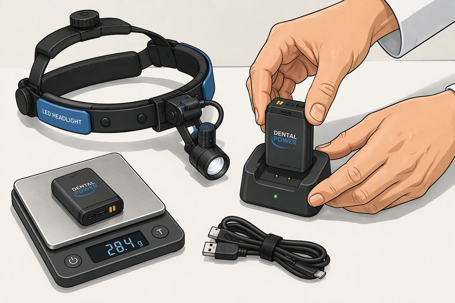
Dental headlight battery design starts with the LED driver’s actual power demand and the clinician’s working routine. A pack must deliver the required illumination for the specified runtime without adding unnecessary weight, excessive surface temperature or inconvenient charging interruptions. Headband-mounted, loupe-mounted and belt-mounted batteries have different mechanical and ergonomic constraints.
For OEMs, the goal is not simply the highest mAh rating. It is a validated combination of usable energy, voltage compatibility, finished-pack mass, protection and charging behavior. A qualified standard cell or existing pack may be suitable; customization becomes valuable when those options cannot meet the device requirements.
Quick Answer: Select a dental headlight battery using measured input power at each brightness setting, the LED driver’s voltage window and a runtime target that includes aging and temperature allowances. Compare finished-pack weight and placement, not cell weight alone. Use a compatible charger and protection circuit, and validate the complete headlight system before making runtime or safety claims.
Key Takeaways
Specify runtime at a defined brightness setting and illumination endpoint, rather than quoting capacity alone.
Lithium-polymer typically describes a pouch-style lithium-ion cell; it is not a separate cathode chemistry such as NMC or LCO.
Balance usable watt-hours against the mass of the housing, cable, connector and electronics.
Charging speed must stay within the selected cell’s limits and the assembled device’s thermal constraints.
Use application-specific validation and relevant battery testing evidence, rather than assuming a certified cell automatically qualifies the whole product.
Part 1: Why Custom Battery Design for Dental Headlights Matters
1.1 Unique Demands of Wearable Dental Lighting
A headlight’s electrical load depends on brightness, driver efficiency and any auxiliary electronics. Its input current can increase as battery voltage falls, especially with a constant-power driver. Engineers should measure the complete load throughout the operating voltage range, not infer current from LED wattage alone.
Battery location matters as much as capacity. A small increase in head-mounted mass can affect comfort and balance, while a belt-mounted pack introduces cable routing, snagging and connector considerations. Assess the assembled product with representative users and the intended mounting arrangement. Do not assume the lightest cell always produces the most comfortable system.
1.2 When Standard Packs Are Enough and When to Customize
Evaluate qualified standard solutions first. They can simplify sourcing and development when voltage, dimensions, runtime and charging interfaces already fit. Customization is justified when the available options cannot satisfy a defined constraint, such as a slim housing, connector location, retention mechanism or charge indicator.
A custom battery solution should address measurable requirements, not merely replace a standard product with a higher capacity label. Check tooling, minimum order quantities, cell availability and replacement strategy before committing to a unique format.
Part 2: Energy Density and Lithium Chemistry Selection
2.1 Separate Cell Chemistry from Cell Format
NMC and LCO describe cathode chemistries. Pouch, cylindrical and prismatic describe packaging formats. Products sold as lithium-polymer batteries are generally rechargeable lithium-ion pouch cells; their voltage limits and performance must still be confirmed from the exact cell specification.
Option | Potential benefit | Selection check |
|---|---|---|
Qualified NMC or LCO-based cells | Energy storage suitable for compact portable products | Specific charge voltage, current capability, cycle data and availability |
LiFePO4 cells | May favor cycle life and thermal stability | Different voltage platform and potential size or weight tradeoffs |
Pouch format | Thin profiles for constrained housings | Mechanical protection, swelling allowance and tab support |
Cylindrical format | Established dimensions and mechanical construction | Diameter, interconnect layout and finished-pack volume |
No chemistry is automatically the best for every dental headlight. Compare qualified cells under the same load, temperature and end-of-life criteria. Cell-level energy density does not include the protection board, enclosure or mounting hardware, so it cannot be treated as finished-pack energy density.
2.2 Match Voltage and Current to the LED Driver
A series connection increases pack voltage; parallel cells increase capacity and available current when correctly matched and interconnected. Choose the arrangement from the driver’s permitted input range, including fully charged voltage, normal discharge voltage and cutoff. A nominal-voltage match alone is insufficient.
Check continuous current, startup transients and allowable voltage sag at low state of charge. Select charger settings from the exact cell specification, including whether the cell requires a conventional or higher charge voltage. Do not bend a standard pouch cell to fit a curved housing. Any unusual cell shape must be specifically engineered and qualified by the cell manufacturer.
Part 3: Battery Size and Capacity Balance for Wearable Packs

3.1 Calculate Runtime Using Usable Energy
For an initial estimate, runtime in hours is usable battery energy in Wh divided by average power drawn from the pack in W. If the power value is measured downstream of a converter, include converter losses. Do not count the same efficiency loss twice.
Illustrative example: A 3.7 V, 2.0 Ah pack stores approximately 7.4 Wh nominally. If testing shows that 80% is usable before the device reaches its defined endpoint, and average pack-side power is 2 W, estimated runtime is about 3 hours: 7.4 × 0.80 ÷ 2. These are example assumptions, not a product specification or guaranteed runtime.
Validate the estimate at each advertised brightness setting. Include driver cutoff, protection thresholds, temperature, cell variation and aged-battery performance. Define whether the endpoint is device shutdown or a minimum acceptable illumination level; a headlight that remains on but is too dim has not necessarily met the intended runtime.
3.2 Design the Complete Wearable Assembly
Set a mass budget for the whole assembly: cells, protection board, housing, cable, connector, clips and fasteners. Specify battery location and center of mass alongside the weight target. More capacity may be useful in a belt pack but unacceptable on a small headband.
Pouch cells need protection against sharp edges, compression and unsupported tabs. Provide swelling allowance based on the cell supplier’s guidance and aging validation. Housing design should address retention, drop exposure, cable strain relief and the specified cleaning agents. A sealed enclosure also changes heat dissipation; evaluate temperature while worn and during charging.
Part 4: Charging Methods and Battery Management
4.1 Choose a Charging Workflow Before Optimizing Speed
Compare an integrated charging port, a removable pack with a charging dock and a spare-pack rotation system. A spare pack may solve availability needs without aggressive fast charging. The right choice depends on turnaround time, handling frequency, cleaning requirements and whether the device is intended to operate while charging.
USB or a dock supplies input power; it does not replace a lithium-ion charging circuit. Use a charger with the correct regulation profile, charge voltage, current and termination behavior. Verify connector polarity, contact resistance and compatibility with approved accessories. USB-C negotiation, where used, must also match the power architecture.
Allow faster charging only when supported by the cell specification and measured thermal performance. Test the worst-case input supply, low initial state of charge and permitted ambient temperature. Charging while the headlight operates requires an appropriate power-path design and separate validation; do not assume a standard charger supports it.
4.2 Distinguish Protection, Charging and Fuel Gauging
A charger controls the normal charging process. A protection circuit or BMS provides defined fault responses. A fuel gauge estimates remaining charge or runtime. These functions may be integrated, but they are not interchangeable.
Function | Design consideration |
|---|---|
Overvoltage and undervoltage protection | Coordinate fault thresholds with cell limits and device cutoff |
Overcurrent and short-circuit protection | Allow legitimate startup loads while limiting fault energy |
Temperature supervision | Use suitable sensor placement and charge limits when required by the design |
Fuel gauging | Validate the low-battery warning against useful remaining lighting time |
Balancing | Consider for multiple series groups; a single-series pack does not need series-cell balancing |
A simple headlight does not necessarily need a communication-enabled smart BMS. Select functions from the system’s risks and user needs. Parallel cells still require appropriate matching, interconnects and fault analysis even when series balancing is unnecessary.
Part 5: Safety, Reliability and Regulatory Compliance
5.1 Validate Mechanical, Thermal and Cleaning Conditions
Test normal use and reasonably foreseeable misuse of the assembled pack and device. Relevant conditions can include drops, cable pull, blocked heat paths, repeated docking, connector wear and incorrect accessory connection. Verify protection behavior and recovery, rather than relying only on board specifications.
Dental cleaning and disinfection are not the same as autoclave sterilization. Do not claim that a lithium battery can tolerate steam, pressure or sterilization temperatures unless the specific assembly and process have been validated. If a pack must be removed before cleaning or sterilization, make that requirement clear in the instructions.
Check user-contact surface temperatures and charging temperatures in the final enclosure. Confirm ingress requirements using the actual seals, ports and mounting arrangement. Battery chemistry alone does not establish an IP rating or eliminate thermal hazards.
5.2 Establish the Applicable Compliance Scope
IEC 62133-2 addresses the safety of portable sealed rechargeable lithium cells and batteries under intended use and foreseeable misuse. Confirm the applicable edition, national requirements and evidence needed for the selected cell and finished battery. A cell report is not automatically a report for a new pack design.
For transport, obtain the applicable UN 38.3 evidence and test summary. PHMSA’s lithium battery test summary guidance explains this documentation requirement. Transport testing does not establish all in-use safety requirements; shipping classification, packaging and carrier requirements must also be assessed.
Device-level medical electrical safety and EMC requirements depend on intended use, product classification and target market. Determine whether IEC 60601 requirements apply with the device compliance team or test laboratory. ISO 13485 concerns a medical-device quality management system; it is not a battery product approval or a guarantee of runtime. Integrate battery evidence into the device’s own verification and risk management.
Part 6: Design Workflow and Manufacturer Partnership
6.1 Build an OEM Battery Specification
Provide the battery manufacturer with the following information before selecting cells:
LED driver input voltage range and measured power at each brightness setting.
Required runtime, acceptable illumination endpoint and end-of-life performance target.
Finished dimensions, mounting position, maximum assembly weight and cable routing.
Connector, polarity, retention and any low-battery indication requirements.
Charging input, turnaround time and whether operation during charging is required.
Operating and storage conditions, cleaning process, target markets and planned production volume.
Agree on sample acceptance criteria before building prototypes. Verify the full lighting system with representative cells and realistic ambient conditions. Record electrical loads, temperatures, charging behavior and usable runtime. Include aged samples or an appropriate aging validation program when lifetime runtime is part of the product claim.
6.2 Plan Traceability and Controlled Changes
Maintain traceability for the cell model and lot, protection hardware, charger settings and finished pack. Changes to the cell, board, connector or firmware can affect runtime and safety. Review their impact and repeat affected tests before approving substitutions.
Large Power can support medical battery integration and custom pack development based on the device’s defined requirements. Share your electrical load, mechanical envelope and charging workflow to assess suitable cells and the necessary validation scope. Do not choose a supplier on capacity or price alone; evaluate documentation, quality controls and long-term sourcing.
A dependable dental headlight battery is the result of coordinated cell selection, wearable packaging, charging design and complete-system testing. Start with the lighting task, then verify that the chosen pack delivers the required usable runtime throughout the intended service conditions.
FAQ
Which battery chemistry is best for dental headlights?
There is no universal choice. Qualified NMC or LCO-based cells may suit compact designs, while other chemistries can be considered where their voltage and size fit. Compare actual cell data. Pouch or lithium-polymer describes a format, not a separate alternative to NMC or LCO.
How should manufacturers balance runtime and weight?
Calculate usable Wh against measured pack-side power, then validate at the advertised brightness. Include aging and temperature allowances and weigh the entire pack assembly. Assess comfort in its intended mounting position rather than judging cell mass alone.
Does a dental headlight need fast charging?
Not necessarily. A charging dock and spare-pack workflow may meet availability needs with less charging stress. If rapid charging is required, the cell’s limits, charger design and enclosure temperature must all support it.
Does a 1S battery pack require cell balancing?
A single-series pack does not require balancing between series groups. A 1S parallel pack still needs suitable cell matching, protection and interconnect design. Fuel gauging and communication are separate features chosen according to device needs.
Can a dental headlight battery be autoclaved?
Do not assume so. Ordinary rechargeable lithium packs are not qualified for autoclave conditions. Follow the validated device cleaning process and remove the pack when instructed. Any claimed sterilization compatibility requires evidence for the specific assembly and process.
What evidence should an OEM request before approval?
Request cell specifications, applicable cell and pack safety reports, transport test documentation, traceability records and agreed validation results. Verify runtime and thermal behavior in the complete headlight. Determine device-level regulatory requirements separately with the responsible compliance team.


