

Load Prioritization, Runtime Calculation, and Controlled Shutdown
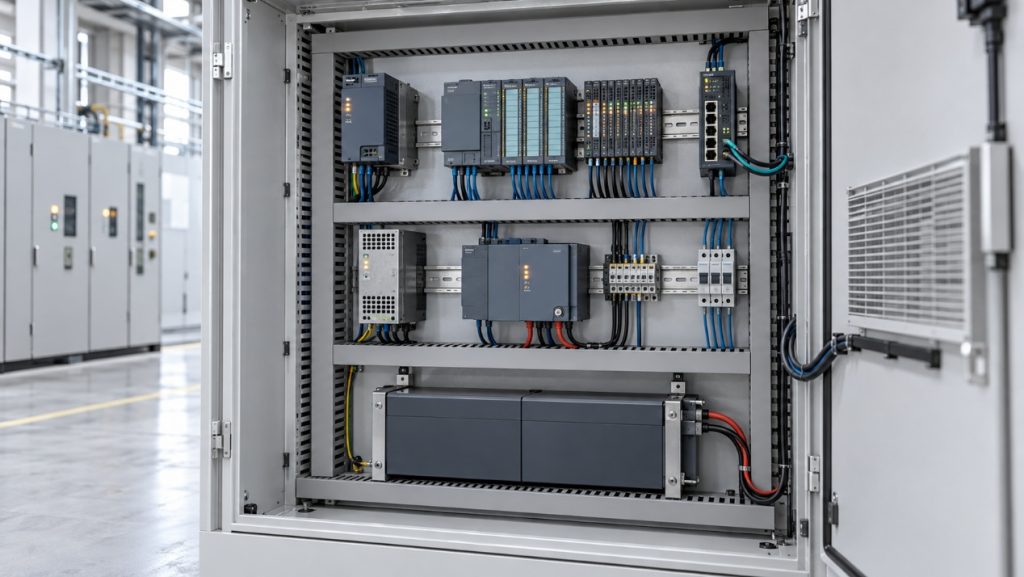
Industrial backup power should be designed around the control functions that must survive an outage, not around battery capacity alone.
A power interruption does not have to last long to disrupt an automated process. A momentary outage may reset a PLC, interrupt an industrial network, blank an HMI, or leave production data incomplete. A longer outage can stop a machine in an uncontrolled state and make recovery more difficult than the original loss of power.
For this reason, battery backup design for an industrial control system should not begin with battery capacity. It should begin with a more practical question: what must the control system accomplish after incoming power is lost?
The answer may be to ride through a short disturbance, keep the process operating until standby generation starts, or provide enough time for a controlled shutdown. Each objective creates a different protected load, runtime target, and UPS architecture.
Part 1: Define the required behavior during an outage
The phrase “backup power” can describe several very different operating goals.
Ride-through covers short voltage dips and interruptions. The objective is to prevent controllers, communication devices, and operator interfaces from restarting during a brief disturbance.
Controlled shutdown provides enough time to stop a process in a defined sequence, save production data, park moving equipment where appropriate, and shut down industrial computers cleanly.
Continued operation keeps selected equipment running for a specified period. This may be required while a generator starts, while a batch reaches a safe stopping point, or while operators respond to the event.
These goals should not be combined without thought. A system intended only to preserve controller logic for five minutes will be much smaller than one expected to operate an HMI, network equipment, instrumentation, and field loads for an hour.
The restart strategy matters as well. When normal power returns, should the system resume automatically, remain stopped until an operator confirms conditions, or restart only after a separate permissive sequence? Backup duration and recovery behavior are parts of the same design problem.
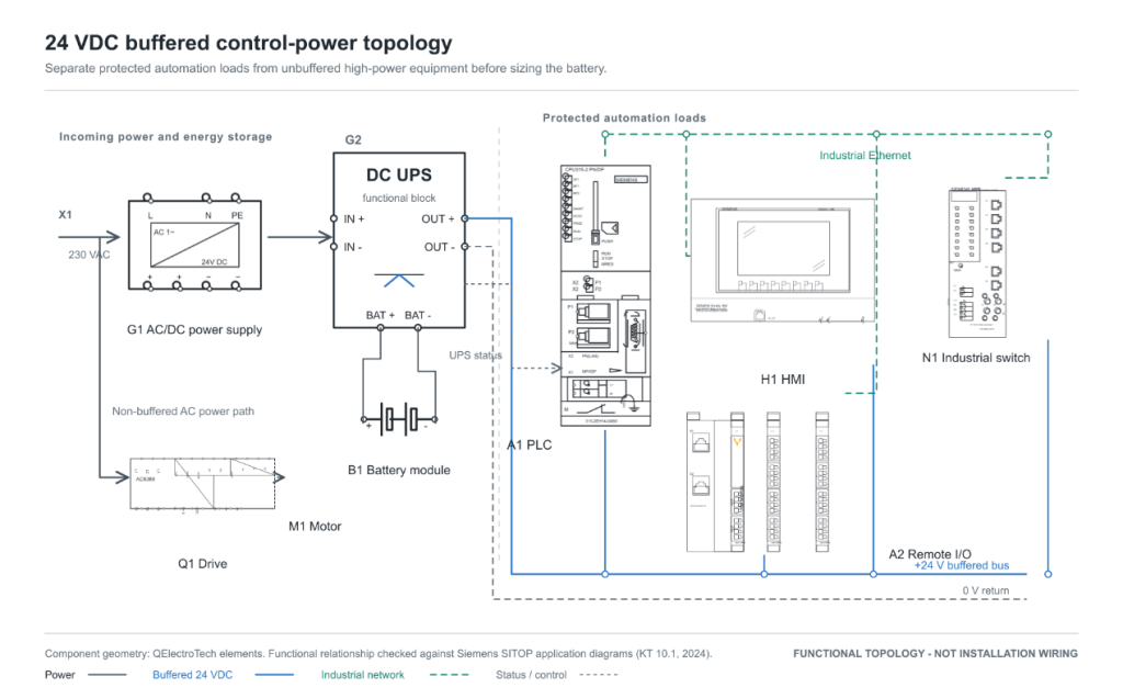
A buffered 24 VDC control bus can keep the PLC, HMI, industrial network, and essential I/O available while the non-buffered AC power path to the drive and motor remains outside the backup boundary.
Part 2: Decide what must remain powered
The most effective way to reduce battery size is not to choose a smaller safety margin. It is to define the protected load correctly.
A typical control system may include:
- PLC or programmable automation controller
- HMI or industrial PC
- Local and remote I/O
- Industrial Ethernet switches
- Communication gateways
- Essential transmitters and sensors
- Safety-related control equipment, where required by the machine safety design
- Interposing relays, contactors, valves, or brakes needed to reach a defined state
Not every device belongs on the backed-up bus. Cabinet lighting, convenience receptacles, cooling equipment, large solenoids, motor starters, drives, and other high-power loads can quickly dominate the energy calculation. Some may still be essential, but their inclusion must follow the process objective rather than convenience.
Document the exact equipment rather than estimating from device categories alone. The installed PLCs and industrial controllers may have different steady-state consumption, expansion-module requirements, communication loads, and startup behavior. An older controller being replaced during a retrofit may not have the same power profile as its successor.
Safety functions require separate attention. Backup power must not prevent a machine from reaching the safe state established by its risk assessment and safety design. Whether a safety controller, brake circuit, valve, or other protective device remains energized cannot be decided from a runtime calculation alone.
Part 3: Choose the power architecture before sizing the battery
Two common approaches are an AC UPS upstream of the control-panel power supply and a DC UPS on the 24 VDC control bus.
An AC UPS can support equipment that requires different AC inputs and may be convenient when the protected system includes an industrial PC, monitor, or other AC-powered device. However, the energy path can include conversion from battery DC to AC and then from AC back to 24 VDC. The UPS may also end up carrying loads that do not need backup unless the protected branch is carefully separated.
A 24 VDC UPS can protect the controller, HMI, network, I/O, and instrumentation directly on the control-power bus. It can make load separation easier and may provide useful status signals or network diagnostics. Its suitability still depends on the required current, battery module, charging system, output voltage range, and compatibility with every protected device.
A 24 V control bus does not mean that any battery marketed as “24 V” can be connected directly. Verify the complete battery voltage range, UPS input and output limits, charging profile, low-voltage cutoff, and the allowable input range of every protected load. Use the approved battery module or a specifically validated battery and power-conversion combination.
Transfer behavior must also be checked. Some loads can tolerate a short interruption; others may reset before backup power becomes stable. The required transfer performance should come from the connected equipment and process behavior, not from a general assumption that every UPS is interruption-free under every condition.
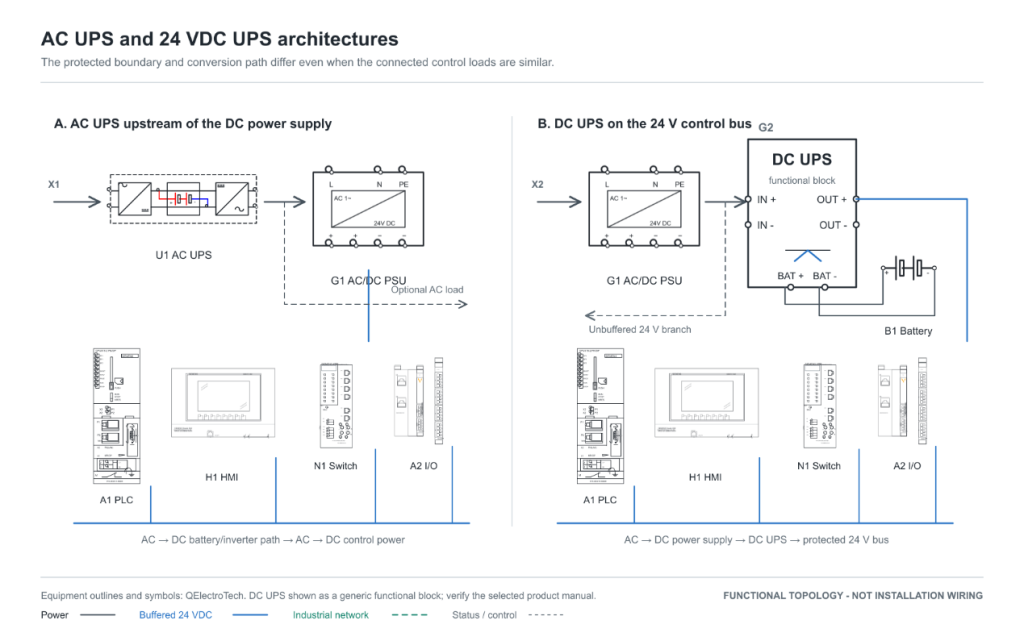
An AC UPS can support mixed AC loads, while a DC UPS can protect a defined 24 V control bus with fewer conversion stages. The correct architecture depends on the connected equipment and outage objective.
Part 4: Build a realistic load list
Runtime calculations are only as useful as the load data supplied to them. Begin with manufacturer data, but verify the installed system by measurement whenever possible.
For DC equipment, power can be estimated from voltage and current:
Power (W) = Voltage (V) × Current (A)
For AC loads, both watts and volt-amperes matter. Watts represent real power, while VA reflects the RMS voltage-current product. The UPS must stay within both its watt and VA ratings. Power factor, nonlinear input currents, and short-duration peaks can therefore affect equipment selection even when the average wattage appears acceptable.
Separate the following values where possible:
- Normal steady-state load
- Highest credible operating load
- Startup or inrush demand
- Loads activated only during shutdown
- UPS self-consumption
- Future expansion allowance
Do not automatically add every device’s maximum nameplate current and treat the result as the normal load. That may produce an unnecessarily large system. The opposite mistake—using only a convenient average reading—can miss communication startup, relay pickup, display brightness, heater operation, or other credible peaks.
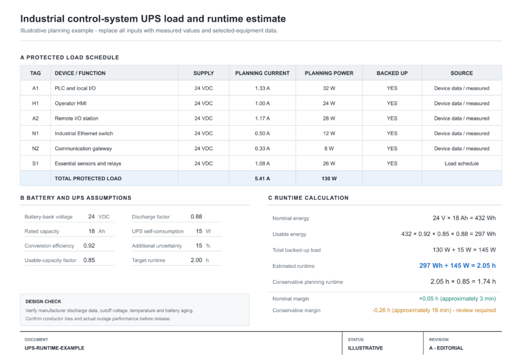
For a representative control panel, a first-pass load schedule might look like this:
| Protected load | Planning power |
|---|---|
| PLC and local I/O | 32 W |
| HMI | 24 W |
| Remote I/O station | 28 W |
| Industrial Ethernet switch | 12 W |
| Communication gateway | 8 W |
| Essential sensors and relays | 26 W |
| Total protected load | 130 W |
Part 5: Convert battery capacity into realistic runtime
The nominal energy of a battery bank is often expressed in watt-hours:
Nominal battery energy (Wh) = Bank voltage (V) × Capacity (Ah)
That value is an energy starting point, not guaranteed runtime. A practical estimate also considers conversion efficiency, the permitted usable portion of the battery, discharge-rate effects, temperature, battery age, cutoff voltage, wiring losses, and the UPS’s own consumption.
A useful planning model is:
Runtime (hours) = Usable battery energy (Wh) ÷ Total backed-up load (W)
where:
Usable battery energy = Nominal Wh × efficiency × usable-capacity factor × discharge factor
The factors below are illustrative assumptions, not universal values. Define what each factor includes so that aging, temperature, discharge-rate effects, cutoff losses, and wiring losses are not counted twice. Likewise, count UPS self-consumption only once and use efficiency data that corresponds to the selected conversion path and load.
Once the protected load and battery-bank assumptions are known, a practical UPS runtime calculator can be used to compare the ideal energy ceiling with a derated estimate that includes conversion efficiency, usable capacity, discharge behavior, and UPS self-consumption.
Consider an illustrative 24 V, 18 Ah battery bank supporting the 130 W control load above. Assume:
- 92% conversion efficiency
- 85% usable capacity
- 88% discharge factor
- 15 W UPS self-consumption
The nominal stored energy is:
24 V × 18 Ah = 432 Wh
The derated usable energy is:
432 Wh × 0.92 × 0.85 × 0.88 ≈ 297 Wh
The total operating load is:
130 W + 15 W = 145 W
The estimated runtime is therefore:
297 Wh ÷ 145 W ≈ 2.05 hours
This result should be treated as a planning estimate. Applying an additional 15% uncertainty allowance would reduce the planning figure to about 1.74 hours, or approximately 1 hour 44 minutes. Manufacturer discharge curves or configuration tools should then be used to verify the chosen battery and UPS combination at the expected load and temperature.
The reason for this second verification is important: amp-hour capacity does not translate linearly into runtime at every discharge rate. Battery terminal voltage, internal resistance, chemistry, cutoff thresholds, and temperature influence how much stored energy is usable before the UPS disconnects the load.
Part 6: Account for battery chemistry, environment, and aging
Battery chemistry should be selected as part of the UPS system, not as an isolated replacement decision. VRLA and lithium-based batteries differ in mass, cycle life, temperature behavior, charging requirements, protection, storage, and maintenance expectations.
The UPS charger and battery-management arrangement must be compatible with the selected battery. Charge voltage, current limits, temperature compensation, protection thresholds, communication, and certification requirements cannot be assumed to transfer from one chemistry to another.
Ambient temperature deserves particular attention in industrial cabinets. Elevated temperature can accelerate battery aging, while low temperature can reduce available capacity. Heat produced by adjacent power supplies, drives, and contactors may make the battery’s local environment different from the temperature measured elsewhere in the room.
A design that meets the target only with a new battery at nominal conditions has little operational margin. Include an aging policy: define how battery condition will be monitored, when capacity will be tested, and at what threshold the battery will be replaced.
Part 7: Plan the shutdown and recovery sequence
Runtime is useful only if the control system knows how to use it.
Where supported, the UPS should provide a mains-failure or battery-mode indication to the controller, industrial PC, or supervisory system. The control logic can then start an orderly sequence, such as:
- Notify the operator and record the event.
- Prevent the start of a new production cycle.
- Complete, hold, or abort the current operation according to the process design.
- Save recipes, counts, logs, and other volatile data.
- Move equipment to a defined condition where the safety design permits it.
- Shut down industrial computers and nonessential loads.
- Maintain only the control and communication functions required until power returns or the battery reaches its limit.
Load shedding can extend the useful backup period considerably. An HMI may be required initially for operator response but not for the entire outage. A nonessential network segment or panel accessory may also be disconnected after shutdown is complete. Each step must be intentional and tested; an unexpected relay drop or communication loss can invalidate the planned sequence.
Recovery also needs validation. Confirm how the UPS behaves when normal power returns, how long the battery requires to recharge, and whether the machine can restart safely after a partial shutdown.
Part 8: Commission the system under representative conditions
The final design check is a controlled outage test performed under approved site procedures.
Before the test, confirm the protected-load boundary, safe machine state, battery charge, expected runtime, and personnel responsibilities. During the test, observe:
- Transfer to battery operation
- Voltage at the most distant protected load
- PLC, HMI, I/O, and network continuity
- Peak current during transitions and shutdown actions
- UPS alarms and status signals
- Operation of the shutdown sequence
- Actual runtime to the defined endpoint
- Recovery after normal power returns
The defined endpoint does not always need to be complete battery exhaustion. It may be completion of the shutdown sequence, arrival of generator power, or a specified minimum state-of-charge margin.
Repeatable periodic testing is more valuable than a successful commissioning test that is never revisited. Loads change, batteries age, cabinet temperatures vary, and maintenance modifications can move equipment onto or off the protected bus. Update the load schedule and runtime assumptions whenever the control architecture changes.
Part 9: A good backup design begins with the process
Battery capacity is only one part of industrial backup-power design. The more important decisions are which functions must survive, how long they must survive, how the system will respond, and how that behavior will be verified.
By defining the outage objective, separating critical loads, selecting the appropriate AC or DC architecture, applying realistic energy derating, and testing the complete shutdown and recovery sequence, engineers can turn a nominal battery specification into a dependable operating strategy.
About the contributor: ParttoGo provides industrial automation sourcing support and practical engineering resources for control systems, electrical panels, and maintenance teams.


