

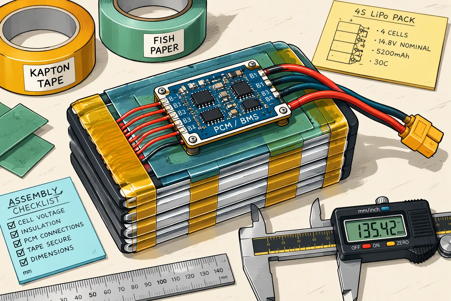
A custom LiPo battery pack is an assembly, not a bare pouch cell. Its finished dimensions depend on the cell drawing, PCM location, interconnects, insulation, labels, wiring and connector arrangement. The enclosure must also accommodate assembly clearance and validated dimensional changes during the intended service life.
For OEM designers, the key is to agree on a controlled finished-pack drawing before freezing the device housing. A cell model code or nominal CAD outline cannot establish the maximum space required by the delivered assembly.
Quick Answer: Specify maximum delivered-pack dimensions and the measurement conditions, then check each local section of the assembly against the minimum available cavity. Add only the layers that actually overlap in that section. Reserve cell-specific lifetime expansion and assembly clearance separately unless they are already included in the agreed envelope. There is no universal 10% swelling allowance, PCM height or wire diameter for all LiPo packs.
Key Takeaways
Use the approved finished-pack drawing, not the cell model number, for enclosure integration.
Define the cell zone, PCM zone and cable zone separately rather than adding unrelated heights together.
Distinguish manufacturing tolerances from lifetime dimensional change and assembly clearance.
Specify foam thickness together with compression force and aging behavior.
Validate fit, retention and thermal conditions using the actual assembled device.
Part 1: Defining Finished Dimensions of Custom LiPo Battery Packs
1.1 Bare Cell Dimensions Versus Finished-Pack Dimensions
LiPo commonly refers to rechargeable lithium-ion pouch cells. A cell code may suggest nominal thickness, width and length under a supplier’s naming convention, but conventions and included features vary. Confirm the actual drawing, tolerance limits and whether seals or tabs are included. A code such as 402025 is not a guaranteed 4.0 × 20 × 25 mm finished-pack envelope.
Contributor | What the drawing should define |
|---|---|
Cell | Body, seal edges, tab geometry and dimensional limits |
PCM | Board location, tallest components, joints and insulation |
Insulation and labels | Material thickness, overlap locations and layer count |
Wiring and sensors | Routing, local height, exit position and strain relief |
Connector | Part number, orientation and applicable external envelope |
Components do not necessarily increase every axis. A PCM beside the tabs may extend the pack length without adding height over the cell body. A board positioned above the cell can instead increase local thickness. Describe the actual layout rather than applying a standard 2–3 mm length addition or a universal board height.
1.2 Separate Delivery Envelope from Installed Space
Define the maximum delivery envelope under agreed inspection conditions, including state of charge, temperature and measurement method. Separately define the installed space needed for mounting materials, assembly access and dimensional change through service life.
Do not call empty enclosure clearance part of the delivered battery unless that convention is explicitly stated. Likewise, do not add insulation or a label twice when it is already included in the finished-pack drawing. Use section views and clear inclusion notes to avoid ambiguity.
Part 2: Calculating Clearance with Tolerance Stacks
2.1 Analyze Each Local Section
Calculate the occupied height where the cell, PCM, wires and other features actually occur. For components arranged side by side, the overall height is governed by the tallest local stack, not the sum of all component heights. Where parts overlap vertically, add their applicable thicknesses and tolerances.
Remaining depth margin = minimum cavity depth − maximum local delivery stack − additional installed layers − validated lifetime growth − required assembly clearance.
This equation assumes that additional layers and lifetime growth have not already been included in the delivery stack. Evaluate length and width using the same location-specific approach. Consider locating-feature tolerances and assembly offsets, not only the outer bounding box.
2.2 An Illustrative Clearance Calculation
Suppose a cell-zone finished stack is specified at 5.40 mm maximum, already including its delivered tape and label. The minimum housing depth is 6.30 mm. A separate installed mounting layer consumes 0.20 mm, the agreed lifetime thickness-change allowance is 0.40 mm, and required assembly clearance is 0.15 mm.
The remaining margin is 6.30 − 5.40 − 0.20 − 0.40 − 0.15 = 0.15 mm. These values are illustrative only; the 0.40 mm allowance is not a recommended universal expansion value. If a PCM beside the cell has a 3.00 mm local height, it is assessed in its own zone rather than added on top of the 5.40 mm cell stack.
Check maximum pack size against minimum cavity size for interference, and minimum pack size against maximum cavity size for retention. Statistical tolerance methods require a justified process model; do not assume independent variations or use a statistical result to overlook a safety-critical interference condition.
Part 3: Pressure and Thermal Limits for LiPo Packs
3.1 Support Without Uncontrolled Point Loads
Protect the pouch from sharp edges, screw tips, rigid bosses and concentrated loads. Do not assume that all compression is forbidden or that every pouch needs a compression fixture. Any specified restraint or pressure must come from the selected cell’s requirements and be validated in the pack design.
Keep seal folds and tabs within their approved geometry. Do not force a completed pack into an undersized cavity or bend a standard cell to make it fit. Confirm the mechanical load path during installation, drops and vibration. Support should not transfer damaging loads through a tab, solder joint or unsupported PCM component.
3.2 Use Cell-Specific Temperature Limits
Charging, discharging and storage can have different temperature limits. Use the exact cell specification and assess temperatures inside the final enclosure, including heat from nearby electronics and the PCM. A general “LiPo operating range” cannot replace these limits.
Remove assumptions that custom cells automatically tolerate continuous use at 85°C or higher. Higher-temperature operation requires explicit supplier qualification and application validation. Thermal expansion of housing and mounting materials also affects fit and retention and should be included where relevant.
Part 4: Retention and Expansion Allowance
4.1 Retention Requires a Force Assessment
Foam, adhesive, holders or other fixtures can provide retention when appropriately designed. Soft foam still applies pressure when compressed. Specify thickness, compression-force behavior, assembly tolerances and expected compression set rather than assuming that foam cannot load the cell.
Verify movement under handling, vibration and drop conditions. A design can avoid interference but still allow the pack to slide, abrade its insulation or pull on wiring. Retention must remain adequate across the permitted cavity and battery tolerances.
4.2 Distinguish Expected Change from Abnormal Swelling
Pouch thickness can change with state of charge, temperature and aging. Obtain cell-specific data under relevant charging, cycling, storage and restraint conditions. Do not apply a universal 8–10% growth after 500 cycles or automatically use 10% of initial thickness as the enclosure allowance.
Gas-induced bulging can also indicate degradation or an abnormal condition. A 5 mm cell growing to 8 mm is not a generic normal-life design rule. Extra enclosure space does not make abnormal swelling safe. Define inspection, service and rejection criteria with the responsible manufacturer.
Document the permitted service-life dimensional envelope and the conditions used to establish it. State whether its growth allowance is additional to manufacturing tolerance. Reserve that space throughout assembly instead of consuming it with an unplanned label, wire loop or foam pad.
Part 5: Adhesive, Foam, Insulation and PCM Mounting
5.1 Count the Actual Material Layers
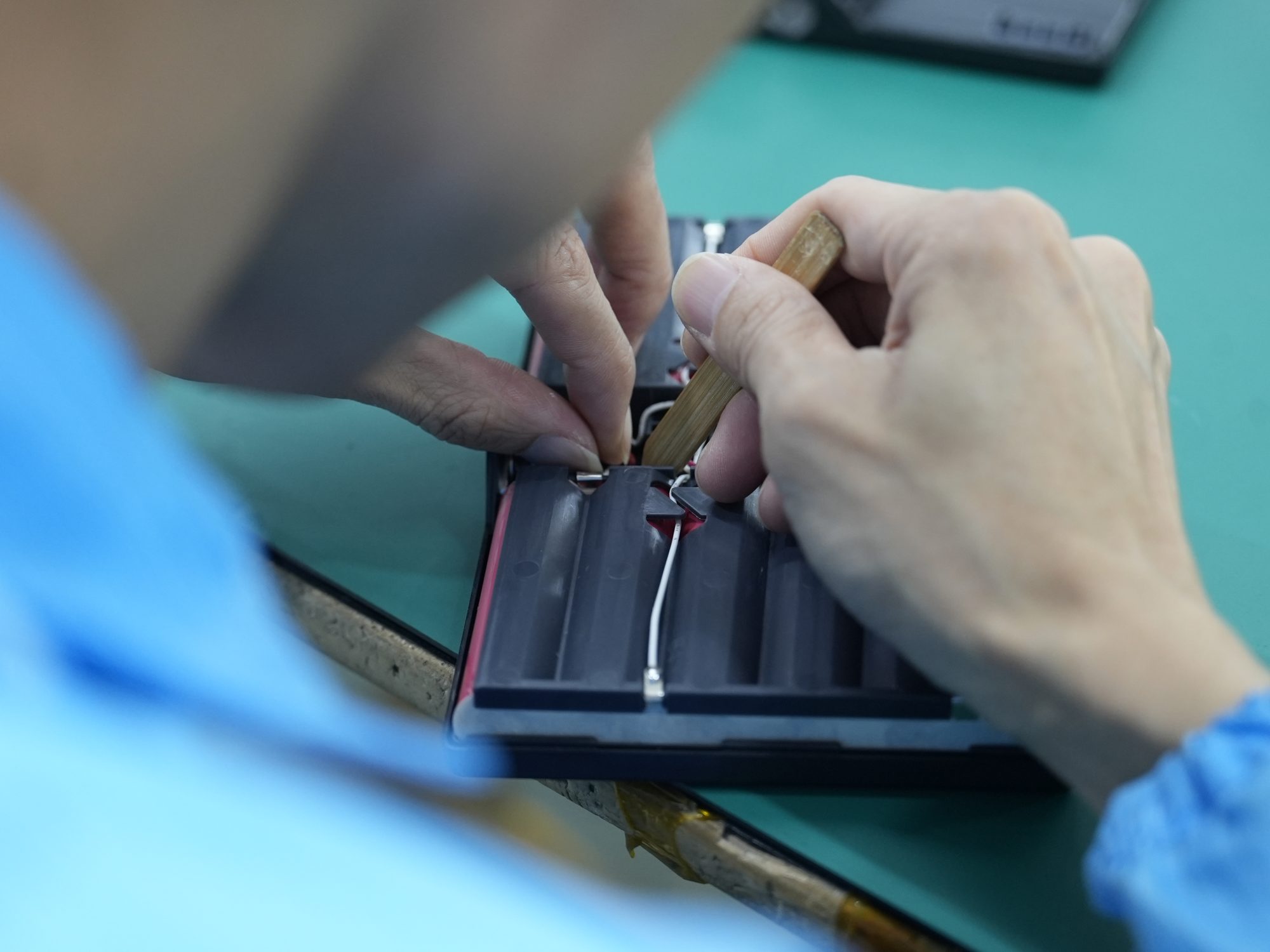
Insulation thickness is product-specific. PET, polyimide and other materials are not interchangeable, and a material name alone does not establish dielectric performance, temperature capability or flammability rating. Select suitable materials and specify their exact grades and dimensions.
Count layers where they exist: film on one face adds one layer; wrapping both faces adds the relevant layers on both faces. Tape overlaps and label edges can create a local maximum. Do not prescribe 0.25 mm for every insulation sheet or assume all plastic films are fireproof.
The PCM envelope includes populated component heights, solder or weld joints, insulation and mounting features. The PCB substrate thickness alone is insufficient. Refer to BMS and PCM design when selecting protection functions, then obtain a layout-specific mechanical envelope.
5.2 Specify Mounting Conditions and Aging
Define adhesive bond-line thickness, tape tolerances, placement and material compatibility. Specify foam at both its free thickness and the intended installed compression range, with the resulting forces. Evaluate aging, temperature and compression set rather than measuring only a fresh compressed sample.
PCM support may use the approved pack structure, a dedicated carrier or an insulated mounting arrangement. It is not universally required to sit rigidly on a pouch terrace. Protect components from mechanical loads and preserve insulation between conductors and the pouch laminate. Confirm repair or replacement access where needed.
Part 6: Cable and Connector Space
6.1 Wire Diameter and Routing
AWG describes conductor size, not the finished wire’s outer diameter. Insulation material and wall thickness vary between products. Use the actual wire drawing and tolerance rather than assigning every 24 AWG wire a 1.6 mm diameter.
Bundle dimensions depend on arrangement, sleeves and crossings. Two wires side by side increase local width; stacked wires increase local height. Reserve bend radius and strain relief from the specified cable and use conditions. Keep routing clear of sharp edges, seals and pressure-sensitive areas.
6.2 Mated Connector and Assembly Access
Identify the connector manufacturer, part number, pinout, polarity and orientation. Reserve space for the mated pair, latch operation and withdrawal path where those functions occur inside the device. External connectors may need a separate envelope rather than being included in the battery body’s dimensions.
Define wire length from an unambiguous datum and show tolerance, exit direction and service slack. A loop must not be pinched during enclosure closure or transfer force into the tabs. Review assembly sequence with the manufacturer before finalizing the housing.
Part 7: Dimensioning and Validation Workflow
7.1 Build a Controlled Finished-Pack Drawing
Define minimum available cavity space, locating features and forbidden zones.
Provide electrical requirements: voltage range, measured load, runtime, charger and temperature conditions.
Select qualified cells and define PCM, sensors, wire and connector requirements.
Create local section stacks and specify maximum delivered dimensions.
Agree on lifetime dimensional change, mounting conditions and assembly clearance.
Approve the drawing revision and fit-validation plan before committing to production tooling.
Provide these inputs for a custom battery solution rather than specifying only a nominal cell size and capacity. A requested maximum envelope must clearly state which features are included.
7.2 Verify Mechanical and Electrical Performance Together
Agree on sample selection, measurement equipment and acceptance criteria. Specify state of charge, temperature, orientation and measurement contact force: excessive measuring force can compress a pouch and understate thickness. Measure critical zones and document results against the drawing.
Validate the assembled product for fit, retention, insulation, cable handling and thermal behavior. Include relevant life conditions and application loads. Capacity and resistance tests support electrical qualification but do not prove mechanical compatibility or long-term safety. Three capacity cycles are not a universal lifetime-validation requirement.
Determine applicable safety and transport evidence from the product and target market with the responsible compliance team. Do not treat UL, IEC, CE, CB, RoHS and national approvals as a mandatory interchangeable checklist for every pack. Testing documentation should match the supplied design and intended application.
Part 8: Common Mistakes and Final Fit Checklist
8.1 Avoid Double Counting and Unsupported Assumptions
Common errors include treating a cell code as a finished drawing, adding a beside-cell PCM height to cell thickness, ignoring tape overlaps, assuming AWG fixes outer diameter, and using a fixed swelling percentage without cell evidence. Another error is subtracting insulation twice after it has already been included in the pack envelope.
Do not describe a pouch seal edge as a universal “gas bag area.” Manufacturing gas-pocket features and finished seal geometry differ by design; use the approved finished-cell drawing. Likewise, avoid universal corner radii or tab-fold dimensions.
8.2 Confirm These Items Before Tooling
Check | Required agreement |
|---|---|
Dimensions | Maximum delivery envelope, datums and local sections |
Clearance | Minimum cavity, added installed layers and assembly margin |
Expansion | Cell-specific life conditions and inclusion notes |
Retention | Mounting method, forces and aged performance |
Wiring | Outer diameter, route, bend limits and exit tolerance |
Connector | Mated envelope, orientation and service access |
Verification | Measurement conditions, fit tests and change control |
Confirm sample fit before final production tooling. Control later changes to cells, PCM components, labels, tape, foam and connectors, since any of these can alter the approved envelope. Finished dimensions should be a reproducible assembly specification, not an estimate built from unrelated catalog numbers.
FAQ
Can I size the housing from the LiPo cell model number?
No. Use the exact cell drawing and a separate finished-pack drawing. Model-code conventions vary, and assembled protection, insulation and wiring can change the envelope.
Is 10% swelling allowance enough?
There is no universal answer. Obtain dimensional-change data for the selected cell and relevant life conditions. Distinguish this allowance from manufacturing tolerance and define abnormal-swelling rejection criteria separately.
Should I add PCM height to cell thickness?
Only where the PCM and cell overlap vertically. A beside-cell board is a separate local stack. Section views show which features actually determine maximum height.
Can foam hold the battery without applying pressure?
Compressed foam applies force. Select and validate its installed compression, contact area and aging behavior against the cell’s requirements. Softness alone does not establish safe retention.
Does wire gauge define routing clearance?
No. Use the specified wire’s finished outer diameter, tolerance, bend limits and bundle arrangement. Include sleeves, crossings, strain relief and assembly access.
What should the OEM send before tooling?
Send the minimum available cavity, mounting and forbidden zones, electrical loads, charger requirements, cable and connector details, environmental conditions and service-life targets. Approve a controlled finished-pack drawing and verify samples against the actual device.


