

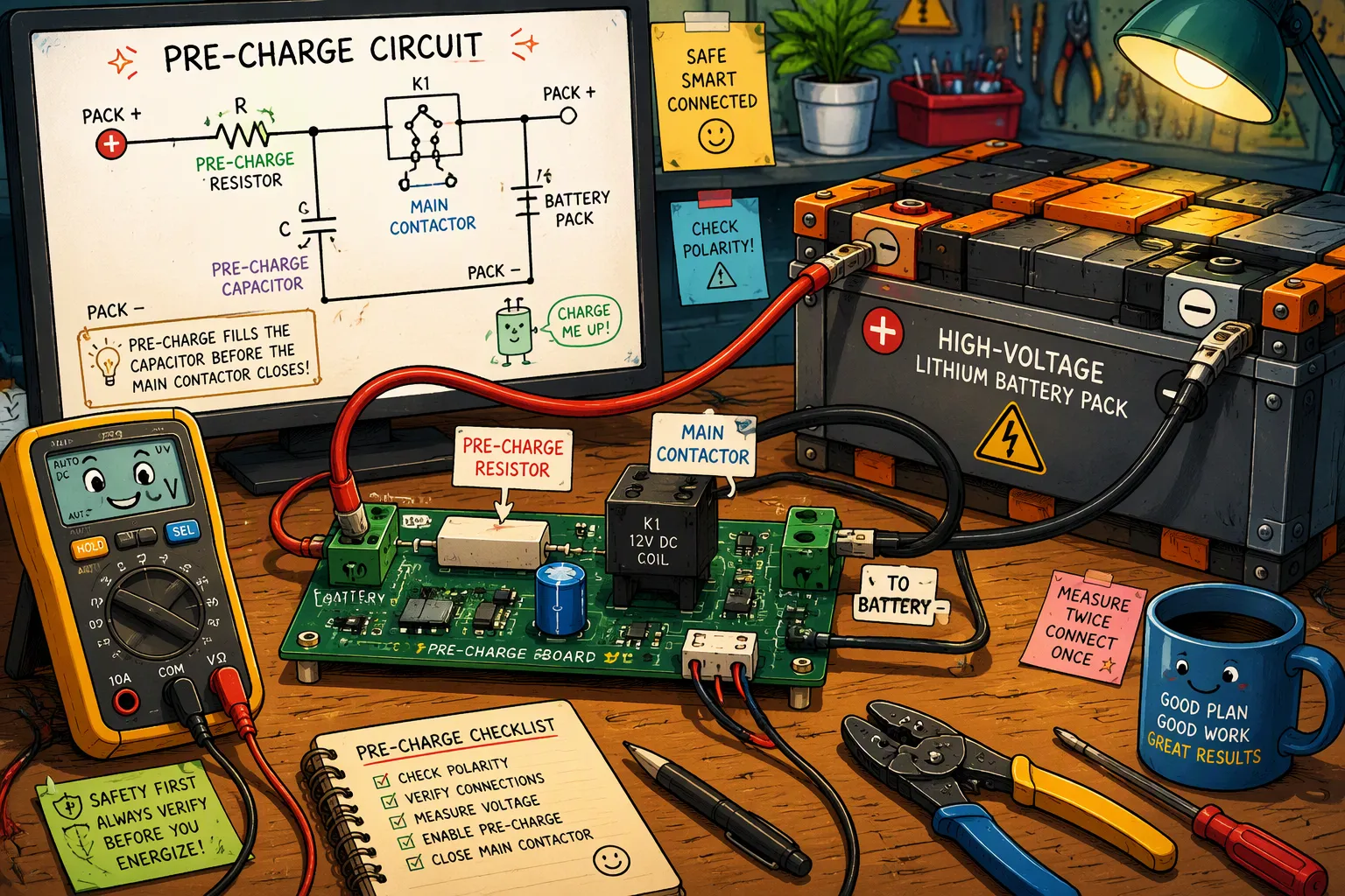
Connecting a 400 V or 800 V lithium battery pack to an uncharged inverter DC link can produce a high inrush current. Its magnitude and duration depend on pack voltage, DC-link capacitance, total loop impedance, cable inductance, switching devices, and the connection point. If the event is not controlled, it can cause arcing, contact erosion or welding, connector damage, and excessive stress on capacitors and conductors.
A pre-charge circuit limits this transient through a resistor and a controlled relay, contactor, or solid-state path before the main power path closes. Proper pre-charge design protects connectors, contactors, capacitors, and power electronics in transportation, industrial, robotic, and infrastructure systems.
Quick Answer: Size a pre-charge circuit from maximum pack voltage, worst-case DC-link capacitance, allowable initial current, target voltage ratio, component tolerances, leakage load, and permitted startup time. Select resistance from both the initial-current limit and the RC timing requirement, then verify pulse energy, peak voltage, repetition rate, switch ratings, BMS voltage feedback, timeout behavior, and main-contactor closing current in the complete system.
Key Takeaways
Without a pre-charge circuit, connecting a high-voltage battery can cause a huge current surge. This surge can weld contacts and destroy connectors.
A pre-charge circuit uses a resistor to limit the inrush current. This lets capacitors charge slowly and safely.
Choose the right resistor by calculating the energy it must absorb. The resistor must handle the capacitor’s stored energy without overheating.
The BMS controls and supervises the pre-charge sequence. It should close the main contactor only after the measured DC-link voltage is sufficiently close to pack voltage and before the pre-charge timeout expires.
Protect the system with fuses, voltage monitoring, and temperature sensors. These prevent damage and ensure long-term reliability.
Part 1: Inrush Current Problem and Pre-Charge Principle
1.1 Connector Damage and System Risks in HV Packs
A high-voltage lithium battery pack can supply substantial fault energy. At initial connection, an uncharged DC-link capacitor presents a low-impedance transient load. The resulting current is limited by the pack, capacitor ESR, cables, busbars, connectors, contactors, and stray inductance; it must be calculated and validated for the actual system.
Parameter | Value / Observation |
|---|---|
Peak inrush current (no pre-charge)Application-dependent; calculate from the actual circuit | |
Example peak (80 V LiFePO4 pack)Not a universal value; verify by analysis and test | |
Typical total loop impedanceDetermined by cells, busbars, cables, connectors, and switches | |
Consequence | Severe contactor contact welding |
The mechanism is straightforward. DC-link capacitors charge almost instantaneously, with dv/dt limited only by parasitics. This produces large I²t stress and arcing. Contacts can liquefy and weld shut. Weld detection is treated as mandatory in high-inrush regions, which confirms that welding is a recognized and expected failure mode when pre-charge is absent. The source does not quantify welding frequency, but the risk is well established.
1.2 Pre-Charge Principle: RC Time Constant Soft-Start
A pre-charge circuit inserts a current-limiting resistor in series with a smaller relay. This resistor sits in parallel with the main contactor. The sequence unfolds in five steps:
The main contactor remains open while capacitors are uncharged.A suitably DC-rated pre-charge relay, contactor, or solid-state switch closes, directing current through the current-limiting resistor.
Capacitors charge gradually, preventing a sudden inrush.
The system monitors until approximately 90% of the supply voltage is achieved.
The main contactor closes, full power applies, and the relay opens.The main contactor should close only after the DC-link voltage has risen sufficiently and while the pre-charge path is still closed. After the main path is verified, the controller opens the pre-charge switch so the resistor does not carry continuous load current. Completion should be based on measured voltage difference, voltage-rise behavior, and a calibrated timeout. A 90–95% voltage ratio is common, but it is not universal; the allowable residual voltage must be derived from the main contactor’s permitted closing current and the total circuit impedance.
Part 2: Component Selection for Pre-Charge Circuit Design
2.1 Resistor Sizing for Power and Pulse Energy
The pre-charge resistor converts most of the energy required to charge an initially discharged DC-link capacitor into heat. For an ideal RC charge from 0 V, this energy is approximately E = 0.5 × C × V². A 60 mF capacitor charged to 800 V therefore represents 19,200 J, which is an unusually demanding example. The selected resistor or resistor bank must be qualified for the actual pulse energy, peak voltage, pulse duration, repetition rate, mounting, ambient temperature, and end-of-life conditions. Apply the component manufacturer’s pulse-load curves and documented design margin rather than a universal multiplier.Resistance determines both the initial current and the charging time. For an ideal RC circuit, Vdc(t) = Vpack × (1 − e^(−t/RC)). Reaching 99% in 2 seconds requires about 4.605 time constants, so τ ≈ 0.434 s and R ≈ 7.24 Ω for 60 mF. A nearby standard value can be considered only after checking initial current, resistor pulse capability, voltage rating, tolerance, bus capacitance tolerance, and the permitted contactor closing current.Initial resistor power is P0 = V²/R and then decays as the capacitor charges. Continuous wattage alone does not determine suitability. For a 48 V, 30,000 µF system, the ideal charge energy is about 34.6 J, but whether a 100 Ω resistor survives depends on its pulse-energy curve, element voltage limit, construction, mounting, temperature, and required cycle interval. Do not infer pulse capability from a 50 W or 10 W continuous rating alone.
Temperature rise demands attention. Although pre-charging lasts only seconds, large heat releases instantly. The resistor surface temperature must stay within the component’s maximum operating temperature. Aluminum-housed and thick-film power resistors are common choices. Low resistance drift is required, and the resistor’s voltage rating must exceed the system’s maximum DC-bus voltage. Individual pulses up to 1,000 V can be handled without additional cooling if correctly designed. High pulse frequencies or continuous loads may require thermal optimization via aluminum housings.Calculations should use the maximum credible pack voltage and the worst-case DC-link capacitance, resistance tolerance, temperature, and repetition pattern. Establish design margin from the resistor manufacturer’s pulse, voltage, temperature, and life data and validate it in the complete assembly.
2.2 Relay, Contactor, and MOSFET Topologies
The switching element in the pre-charge path carries the current during capacitor charging. Three technologies dominate this role.
Technology | Advantages | Disadvantages |
|---|---|---|
Electromechanical relays / small contactors | Traditional, established approach for the pre-charge path | Face voltage stress; can suffer from arcing or welded contacts if misused |
MOSFET-based solid-state switches | Fast, repeatable, minimal contact wear; can be implemented as a compact, highly reliable solid-state relay | Higher component cost and more design effort up front |
Electromechanical relays remain the established approach for Pre-Charge Circuit Design in high-voltage lithium battery packs. These components face voltage stress and can suffer from arcing or welded contacts if misused. MOSFET-based solid-state switches offer fast, repeatable operation with minimal contact wear. They can be implemented as compact, highly reliable solid-state relays using isolated drivers. The trade-off is higher component cost and more design effort up front.The BMS controls a topology-specific switching sequence. In one common two-contactor architecture, one main contactor closes first, followed by the pre-charge switch; other systems place pre-charge on a different side or use a solid-state path. The controller monitors pack voltage, DC-link voltage, elapsed time, and, where available, pre-charge current. It closes the bypass contactor only when the residual voltage and predicted closing current are within validated limits, then confirms the main path before opening the pre-charge switch.
Part 3: Pre-Charge Calculations and Timing Sequence
3.1 Resistor Value and Inrush Current Calculation
For an ideal RC charge, the general timing equation is R = −t / [C × ln(1 − k)], where k is the target DC-link-to-pack voltage ratio. The table uses R = t/(5C), the special case for approximately 99.3% charge after five time constants. The initial-current constraint is R ≥ ΔV₀/Imax, based on the initial voltage difference. Use the stricter result and then check tolerances, leakage load, and pulse limits.
Purpose | Formula | Variables |
|---|---|---|
Resistance from desired charging time | R = t / (5 × C) | R in Ω, t in s, C in F |
Minimum resistance from current limit | R_min = U / I_max | U in V, I_max in A |
Maximum inrush current | I_max = U / R | I_max in A |
Energy absorbed per pre-charge cycle | E = 0.5 × C × U² | E in J |
Average power over repeated cycles | P_avg = E_sum / t_sum | P_avg in W |
Consider a 1000 µF DC-link capacitor in an 800 V lithium battery pack. Target a one-second charge time. Using the timing formula, R equals 1 divided by the product of 5 and 0.001, which gives 200 Ω. Peak inrush current at power-on equals 800 V divided by 200 Ω, or 4 A. If the maximum allowable inrush current is 6 A, the minimum resistance becomes 800 V divided by 6 A, approximately 133 Ω. The designer selects 200 Ω. This choice satisfies both the timing requirement and the current limit.
The resistor must absorb the capacitor’s stored energy each cycle. Energy per pre-charge equals 0.5 multiplied by capacitance multiplied by voltage squared. For 1000 µF at 800 V, this equals 0.5 multiplied by 0.001 multiplied by 640,000, or 320 J. The resistor’s pulse energy rating must exceed this value with a safety margin.
Repeated pre-charge cycles require thermal evaluation. If the system performs three pre-charges within ten seconds, total energy equals 960 J. Average power dissipation equals 960 J divided by 10 s, or 96 W. The resistor must handle this thermal load without exceeding its maximum temperature rating. Pre-Charge Circuit Design must account for scenarios where the main contactor opens and closes repeatedly after a fault condition. The resistor should be evaluated for how many times it may be cycled in quick succession without overheating.
3.2 Timing Duration and Contactor Closure Logic
The RC time constant τ equals the product of resistance and capacitance. For 200 Ω and 1000 µF, τ equals 0.2 seconds.
Time Constant | Approximate Capacitor Charge Level |
|---|---|
≈ 95% | |
5τ | ≈ 99%In the ideal example, three time constants equal 0.6 seconds and produce about 95% charge. This is a calculation reference, not a command to close after a fixed delay. The BMS should verify the measured DC-link voltage, residual voltage across the main contactor, voltage-rise rate, sensor plausibility, and timeout status before closing. Leakage loads or an open resistor can prevent the expected curve even when the timer expires. |
The BMS follows a defined sequence for safe pre-charge completion:
Safety checks execute first to verify system integrity.
The pre-charge path closes, allowing current flow through the resistor.
The resistor initiates the battery pack voltage ramp test.
Pack voltage rises toward the pre-charge voltage threshold.
The BMS confirms voltage matching between pack and capacitor.
The main contactor closes to complete the connection.The closing criterion should limit the residual voltage across the main contactor so the predicted closing current remains within its verified capability. Accurate pack-side and load-side sensing is especially important at high voltage. The BMS should also detect an implausibly fast rise, a stalled rise, reverse voltage, or disagreement between redundant measurements where required by the risk analysis.
Early contactor closure, where the main contactor engages before full pre-charge completion, can lead to high inrush currents and damage. Long or variable pre-charge times may indicate insufficient resistor sizing or faulty sensors. Excessive resistor heating or missing diagnostic data can signal thermal or control problems, risking system failure.
Proper validation of the threshold helps avoid contactor welding or premature failure. These principles apply across industrial sectors, including medical equipment backup systems powered by LiFePO4 batteries, robotics power management using NMC packs, and infrastructure transportation applications. Each system demands careful timing verification and voltage monitoring for reliable long-term operation.
Part 4: Implementation and Protection Strategies
4.1 Resistor Protection with Fusing and Monitoring
A pre-charge resistor experiences a defined pulse during each successful startup and potentially greater stress during abnormal or repeated attempts. The BMS should supervise pack voltage, DC-link voltage, elapsed time, and, where justified, current or resistor temperature. A dedicated fuse or fusible element may be added when fault analysis shows it is needed, but it is not universal; its DC voltage rating, interrupting rating, time-current behavior, and coordination with the main fuse and switching devices must be verified.
Monitoring Type | Implementation Detail | Protective Purpose |
|---|---|---|
Tracks DC-link voltage during pre-charge; uses threshold detection with hysteresis control to confirm complete charging (typically ~90–95% of battery voltage) before main circuit engagement | Prevents main circuit activation before capacitors are adequately charged | |
Current sensing | Detects abnormal pre-charge behavior such as open circuits, short circuits, or incomplete pre-charge conditions | Triggers alarms, prevents drive operation, or initiates safe shutdown |
Temperature sensing on pre-charge resistors | Monitors thermal stress on resistors that dissipate substantial energy during charging cycles | Prevents thermal damage and premature component failure |
Timer-based supervision | Configurable delay timers (100ms to 5 seconds) supervise pre-charge duration | Ensures pre-charge completes within safe time bounds; timeout protection prevents thermal damage |
Diagnostic algorithms | Monitor resistor degradation, contactor wear, and capacitor health; provide early warning indicators | Enables predictive maintenance and prevents system damage from degraded components |
Thermal management in pre-charge resistor design is a critical engineering consideration that directly impacts system reliability and operational longevity. During the charging cycle, the pre-charge resistor must dissipate substantial energy, converting electrical energy into heat. If this thermal stress is inadequately managed, it can lead to premature component failure, degraded performance, and potential safety hazards.A dual-path architecture commonly combines a current-limited pre-charge path with a low-loss main bypass path. Component current, capacitance, and timing ranges must come from the actual design rather than generic limits. Diagnostics can compare the measured voltage-rise curve with the expected RC envelope to detect an open resistor, shorted pre-charge switch, excessive load, changed capacitance, or sensor fault. Repeated retry attempts should be limited and thermally supervised.
4.2 Failure Modes: Welded Contactors and Detection
Contactor welding is a serious high-voltage failure mode. A welded device cannot provide the commanded isolation, although another series contactor may still interrupt the circuit in a redundant architecture. The BMS should perform topology-appropriate weld detection, block unsafe restart, record the fault, and preserve the remaining isolation path where possible.
Detection Method | Working Principle |
|---|---|
With the contactor commanded open, the voltage across its two terminals is measured. A healthy open contact shows a substantial voltage (up to full bus/supply voltage); a welded contact reads near zero because current still flows through it. | |
Bus-to-source comparison | On the charging path, after both charge contactors are commanded open, the HV bus voltage is compared with the charger/external supply voltage. If the two voltages track each other instead of diverging, current is still flowing where it should not — indicating a weld in that path. |
Sequenced isolation testing | When multiple contactors share a current path, they are opened one at a time and the voltage is re-checked after each step. This localizes which specific contactor has welded, rather than only confirming a weld exists somewhere in the path. |
These weld checks are typically performed at moments when the system already expects the contactors to be open and no drive torque is required — for instance right after a charging session ends, or during the shutdown sequence before the vehicle is left unattended. They are not run continuously during normal driving, because deliberately opening a contactor under load just to test it would subject it to the same arcing stress the test is designed to detect. Proper Pre-Charge Circuit Design ensures these detection methods operate reliably across the system lifetime.
The design flow follows five logical steps. Engineers define system parameters, including battery voltage and load capacitance. They select the pre-charge resistor value and its energy rating. They choose a compatible relay or contactor. They determine RC timing and BMS control logic. They implement protection through fusing, current monitoring, and timeout supervision.
Proper pre-charge circuit design ensures connector longevity and system safety in high-voltage battery packs. Engineers test under worst-case conditions, such as a fully discharged capacitor, to verify the resistor does not overheat.
This approach scales to 800V systems. Higher voltage demands greater attention to inrush control. The same principles serve medical, robotics, and industrial applications.
FAQ
What resistor type works best for repetitive pre-charge cycling in industrial systems?
Use a resistor or resistor bank with documented pulse-energy, element-voltage, temperature, and repetition capability for the calculated waveform. Wirewound, thick-film, and other power-resistor technologies can all be suitable when their manufacturer data supports the duty cycle. Validate resistance tolerance, mounting, cooling, vibration, and recovery time between attempts.
How does pre-charge design differ for LiFePO4 versus NMC lithium battery packs?
Pre-charge sizing is driven primarily by maximum pack voltage, initial voltage difference, DC-link capacitance, source and loop impedance, allowable current, and startup time—not chemistry alone. LiFePO4 and NMC use different cell voltages and series counts, but packs of either chemistry can have the same bus voltage. Compare complete pack specifications rather than assuming that NMC automatically requires a larger resistor.
What happens if the BMS detects a pre-charge timeout failure?
The BMS should abort the startup, command the contactors to the validated safe state, inhibit automatic retries beyond the permitted limit, and log diagnostic data. The fault investigation should cover the resistor, pre-charge switch, contactors, voltage sensors, wiring, load-side short or leakage, and DC-link capacitance.
Why does an 800V battery system need stricter pre-charge control than a 400V system?
For the same capacitance and initial conditions, stored energy scales with voltage squared, so 800 V represents four times the ideal capacitor energy of 400 V. Higher voltage also increases insulation, creepage, switching, measurement, arc-control, and component-voltage requirements. Actual pre-charge energy and current still depend on the complete circuit and initial voltage difference.


