

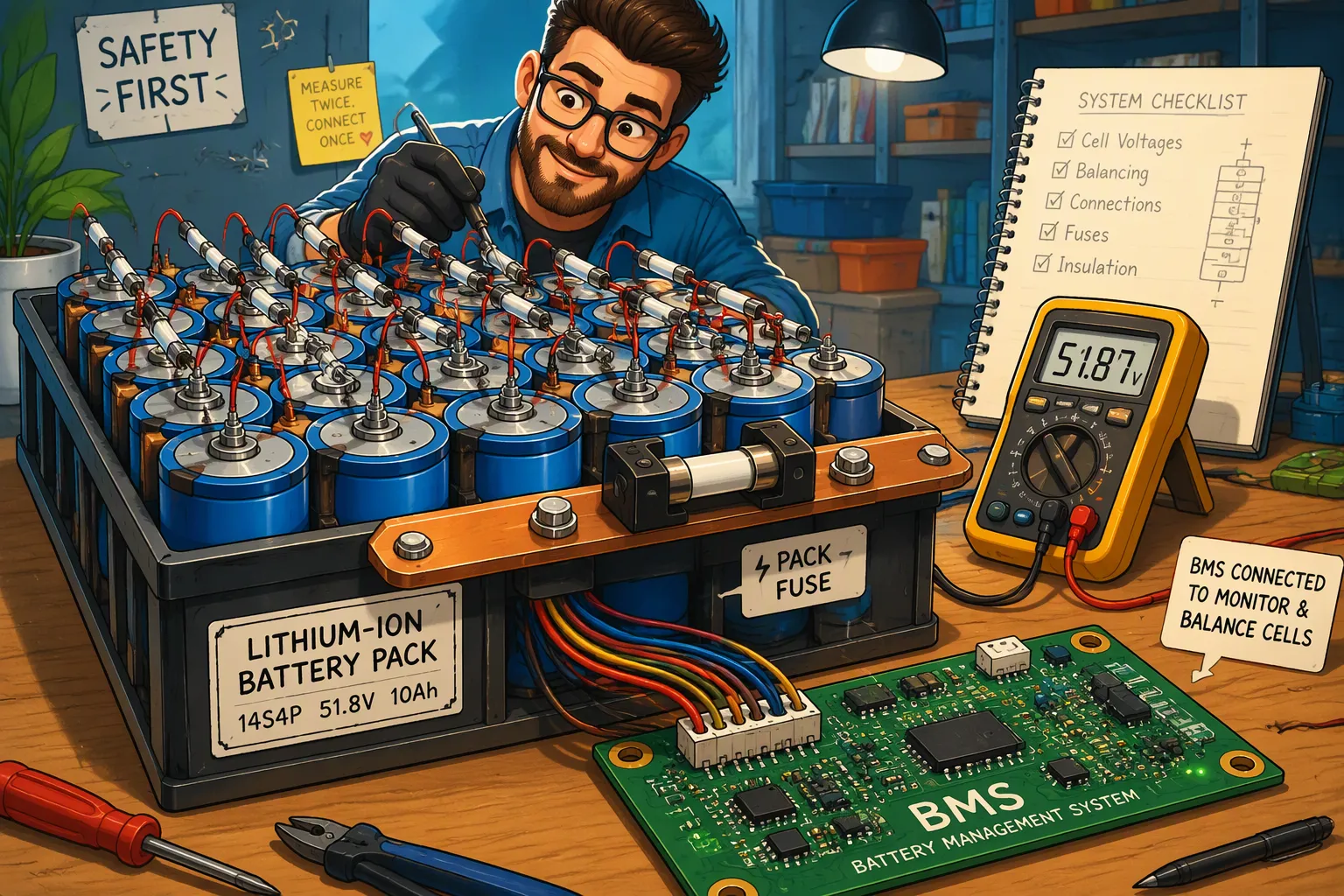
Lithium battery protection is not a contest to see which device opens first. The BMS, contactors or MOSFETs, pack fuse, and any cell- or module-level fusible links must each address a defined fault range. A design is successful when normal current and permitted pulses pass without interruption, recoverable faults are handled by active protection, and severe faults are cleared before conductors, cells, switching devices, or the enclosure exceed their withstand limits.
Quick Answer: Select a battery pack fuse from the maximum DC voltage, normal current profile, ambient temperature, prospective short-circuit current, required interrupting rating, time-current curve, total clearing I²t, and the withstand capability of cables, busbars, contactors, cells, and downstream equipment. Coordinate it with the BMS using manufacturer curves and fault testing. Do not rely on a universal current margin or fixed I²t ratio.
Key Takeaways
The BMS normally handles monitored, recoverable overcurrent events; the fuse provides independent protection for severe faults or failed switching devices.
Cell-level fusible links are mainly useful in parallel groups to limit current contributed by healthy cells into a faulted branch.
A cell fuse may not interrupt an internal short using only the faulted cell’s own current.
Voltage rating, DC interrupting rating, time-current behavior, thermal derating, and I²t are all essential selection parameters.
Final coordination requires the actual fuse manufacturer’s data and testing of the complete battery assembly.
Part 1: Define the Function of Each Protection Layer
1.1 BMS, Switching Device, and Main Fuse
The BMS and PCM monitor current, cell voltage, pack voltage, and temperature. In a contactor-based pack, the BMS commands the contactors to open. In a lower-voltage pack, it may turn off charge and discharge MOSFETs. These active devices can provide fast, resettable protection for overloads and short circuits within their rated safe operating area.
The main fuse is independent of BMS software and control power. It protects against high-energy faults that exceed the switching device’s interrupting capability, as well as faults that remain energized if a contactor welds or a MOSFET fails short. The fuse is therefore a final protective barrier, not a substitute for correct sensing, pre-charge, contactor selection, conductor sizing, or fault containment.
Protection Element | Primary Function | Important Limitation |
|---|---|---|
BMS current protection | Detect overload or short circuit and command a controlled shutdown | Depends on sensors, power, software, and an operable switching device |
Contactor or MOSFET | Interrupt current when commanded | Has finite breaking capacity and may fail short or weld under severe stress |
Main pack fuse | Clear high-energy faults independently | One-time device; must be replaced and the root cause investigated |
Cell or module fusible link | Limit fault contribution from parallel branches | Does not guarantee interruption of every internal cell fault |
1.2 Cell-Level Fusible Links
Individual cell fusing is most relevant when many cells are connected in parallel. If one cell or connection develops a low-impedance fault, the other parallel cells can feed current into that branch. A fusible link between the affected cell and the common bus may open and limit the energy contributed by the healthy cells.
This distinction matters: an external link responds to current flowing through the link. An internal short contained within one cell may not produce sufficient external current to melt it. The design must also consider the cell’s own venting behavior, internal protection features, spacing, propagation barriers, and pack-level shutdown strategy.
After a cell link opens, the pack has changed electrically. Remaining cells carry more current, capacity is reduced, and current sharing may become less uniform. The BMS should detect or infer the abnormal condition where feasible, record a fault, and apply the system’s service or shutdown policy. Continuing operation without evaluation should not be presented as the default objective.
Part 2: Calculate the Fault and Operating Conditions
2.1 Normal Current Is a Profile, Not One Number
Record maximum continuous current, permitted overload duration, repetitive pulses, regenerative or charging current, startup inrush, pre-charge behavior, ripple current, and expected duty cycle. Include tolerances and operation at the highest enclosure temperature. A fuse that carries a nominal current on a laboratory bench may run much hotter inside a sealed pack beside cells, busbars, and contactors.
Normal-operation current and BMS thresholds must remain below the fuse’s minimum melting region with suitable margin. The margin is determined from the manufacturer’s time-current curves and application guidance, not from a generic percentage.
2.2 Prospective Short-Circuit Current
Do not assume that every 48 V LiFePO4 battery produces the same fault current. Prospective short-circuit current depends on cell DC resistance, series and parallel configuration, state of charge, temperature, cell aging, busbars, cables, connectors, switching devices, and fault location. Calculate conservative cases and verify them where practical.
A simplified initial estimate may divide open-circuit voltage by total loop resistance, but dynamic cell behavior and current limiting make the real waveform more complex. For high-energy packs, use qualified cell data, impedance measurements, circuit simulation, and controlled testing. Evaluate faults at the pack terminals and at internal locations because loop impedance and available current differ.
2.3 Component Withstand Limits
The fuse must clear before the fault exceeds the verified withstand of cables, busbars, contactors, MOSFETs, connectors, PCB conductors, insulation, and downstream equipment. Relevant limits may be expressed as peak current, duration, temperature rise, I²t, or a device safe operating area. The lowest credible withstand can become the controlling design constraint.
Part 3: Select the Main Pack Fuse
3.1 Voltage and Interrupting Rating
The fuse’s DC voltage rating must equal or exceed the maximum circuit voltage under all operating and charging conditions. DC interruption is demanding because there is no natural current zero as in AC systems. Use a fuse specifically rated for the DC voltage and fault conditions of the application.
The interrupting rating must exceed the prospective fault current at the relevant DC voltage. Do not transfer an AC rating to a DC circuit or assume that a fuse family always provides the same rating across every voltage and part number. Confirm the exact device datasheet, approvals, installation method, and any required fuse holder.
3.2 Current Rating and Thermal Derating
The fuse must carry the validated normal current profile without unacceptable temperature rise or fatigue. Account for enclosure ambient, heat from adjacent components, terminal size, conductor cross-section, airflow, cycling, and mounting orientation. Follow the manufacturer’s derating data; IEC 60269 or UL 248 classification alone does not supply a universal derating percentage for every installation.
A higher ampere rating is not automatically safer, and a fuse rating does not need to sit below the cell’s maximum continuous discharge rating as a universal rule. The selection must protect the actual conductors and components while remaining stable during permitted operation.
3.3 Time-Current Curve and I²t
The time-current curve shows how long a fuse takes to open at different current levels. Use both minimum melting or pre-arcing information and total clearing information. At high current, a current-limiting fuse can reduce peak current and total energy, but its performance depends on the available fault current and circuit conditions.
I²t is the time integral of current squared. The approximation I²t = I² × t is useful only when current is effectively constant. Actual fuse fault current changes as the element heats, arcs, and limits current, so manufacturer total-clearing I²t data or waveform integration is preferable.
Part 4: Coordinate the Fuse with the BMS and Contactors
4.1 Desired Operating Sequence
For recoverable overloads within the switching device’s capability, the BMS should normally detect the event and open the contactor or MOSFET before the fuse is damaged. For extreme short circuits, welded contactors, failed MOSFETs, or faults outside the monitored path, the main fuse must clear the circuit within the withstand limits of the assembly.
Pre-charge should control capacitor inrush rather than asking the fuse or contactor to tolerate an uncontrolled surge. Verify pre-charge resistance, time, capacitor tolerance, retry logic, and failure detection. A fuse that opens during a permitted startup event is evidence of a coordination or inrush-control problem.
4.2 Selectivity Between Multiple Fuses
If the design includes cell, module, and pack fuses, compare the downstream device’s total-clearing behavior with the upstream device’s minimum-melting behavior across the full relevant fault-current range. A fixed 1.5:1 I²t ratio is not universally sufficient. Fuse construction, tolerance, preloading, ambient temperature, aging, and the shape of the fault waveform all affect selectivity.
Use manufacturer coordination tables where available. Otherwise overlay time-current tolerance bands and compare I²t data for the exact part numbers. Confirm that an internal branch fault clears the intended downstream link without unintentionally opening the main fuse, while a pack-terminal fault is cleared safely by the main device.
4.3 Protection Is Not Always Fully Selective
At very high fault currents, two fuse curves may converge and full selectivity may be impossible. The safety goal then takes priority over maintaining operation. Document the fault ranges in which selective operation is achieved and those in which multiple devices may open. For medical, industrial, robotic, security, and infrastructure equipment, availability requirements must never override safe fault interruption.
Part 5: Practical Selection Workflow

Define the architecture. Record maximum series voltage, parallel branches, switching devices, conductor sizes, grounding arrangement, and likely fault locations.
Define operating currents. Include continuous load, pulses, charging, regeneration, inrush, pre-charge, ripple, duty cycle, and temperature extremes.
Estimate prospective fault current. Evaluate pack-terminal and internal faults using conservative resistance and cell conditions.
Identify withstand limits. Gather cable, busbar, connector, contactor, semiconductor, and enclosure data.
Screen candidate fuses. Confirm DC voltage rating, interrupting rating, current rating, environmental limits, certifications, and mounting requirements.
Coordinate curves. Compare BMS delays, switching-device breaking capacity, fuse tolerance bands, and pre-arcing and total-clearing I²t.
Evaluate temperature. Test the actual enclosure and terminal arrangement at continuous and cyclic load.
Verify faults safely. Confirm the intended device opens and that arc, pressure, temperature, and let-through energy remain controlled.
Part 6: Verification and Documentation
6.1 Test the Complete Assembly
Component datasheets are necessary but do not replace pack-level verification. Test permitted overloads, startup and pre-charge, BMS current-sensor tolerance, contactor opening, failed-switch scenarios, representative internal faults, and the maximum credible external fault. Use appropriate facilities, remote operation, instrumentation, barriers, and risk controls for destructive testing.
Record current and voltage waveforms, fuse clearing time, peak current, temperature, arc containment, contactor behavior, BMS events, and post-test insulation condition. Confirm that a fuse opening does not create secondary hazards such as exposed live parts or an uncontrolled arc path.
6.2 Standards and Change Control
Select component and product standards according to the market and application. Fuse requirements may involve the IEC 60269 or UL 248 families, while the battery pack and end product may be governed by separate battery, medical, industrial, transport, or functional-safety standards. Compliance with one fuse standard does not establish compliance of the complete battery system.
Control changes to cell model, busbar geometry, cable length, contactor, fuse part number, fuse holder, enclosure, BMS thresholds, and firmware. Any change that alters fault current, thermal conditions, or trip timing requires a coordination review and, where necessary, repeat testing.
Common Mistakes to Avoid
Treating the BMS as a fuse or assuming software protection is independent.
Assuming a cell link will clear every internal cell short.
Choosing a fuse only from nominal current.
Using a fixed current margin or I²t ratio without checking manufacturer curves.
Applying an AC voltage or interrupting rating to a DC battery circuit.
Ignoring enclosure temperature, terminal heating, pulse fatigue, and vibration.
Assuming a generic Class T, gG, or aR fuse is correct without checking the exact part and application.
Failing to investigate the root cause after a fuse opens.
Conclusion
Battery fuse selection begins with fault analysis, not a preferred fuse class. Define what the BMS and switching devices can interrupt, calculate the available fault current, identify the weakest conductor or component, and select a fuse whose voltage, breaking capacity, time-current behavior, and I²t protect the complete system. Then verify the coordination in the actual battery assembly. Large Power can support custom lithium battery solutions with BMS, fuse, contactor, busbar, enclosure, and validation requirements developed together.
FAQ
Can a cell-level fuse stop an internal cell short?
Not necessarily. It mainly interrupts current entering the faulted branch from other parallel cells. An internal short confined to one cell may not send enough current through the external link to open it.
Should the BMS or pack fuse operate first?
For monitored, recoverable overcurrent within the switching device’s capability, the BMS should normally disconnect first. The fuse should clear severe faults, failed switching devices, or conditions outside active protection capability.
Is a 1.5:1 I²t ratio enough for fuse selectivity?
It is not a universal rule. Use manufacturer coordination data, tolerance bands, pre-arcing I²t, total-clearing I²t, and the full prospective fault-current range, followed by verification testing.
How do you determine the required interrupting rating?
Calculate the maximum prospective short-circuit current at the fuse location under conservative voltage, resistance, temperature, and state-of-charge conditions. Select a DC-rated fuse whose interrupting rating exceeds that current at the applicable voltage.
Why can a correctly rated fuse still overheat?
High enclosure temperature, undersized conductors, loose terminals, poor airflow, repeated pulses, or an unsuitable holder can increase fuse temperature. Validate the complete mounting arrangement under the real duty cycle.


