

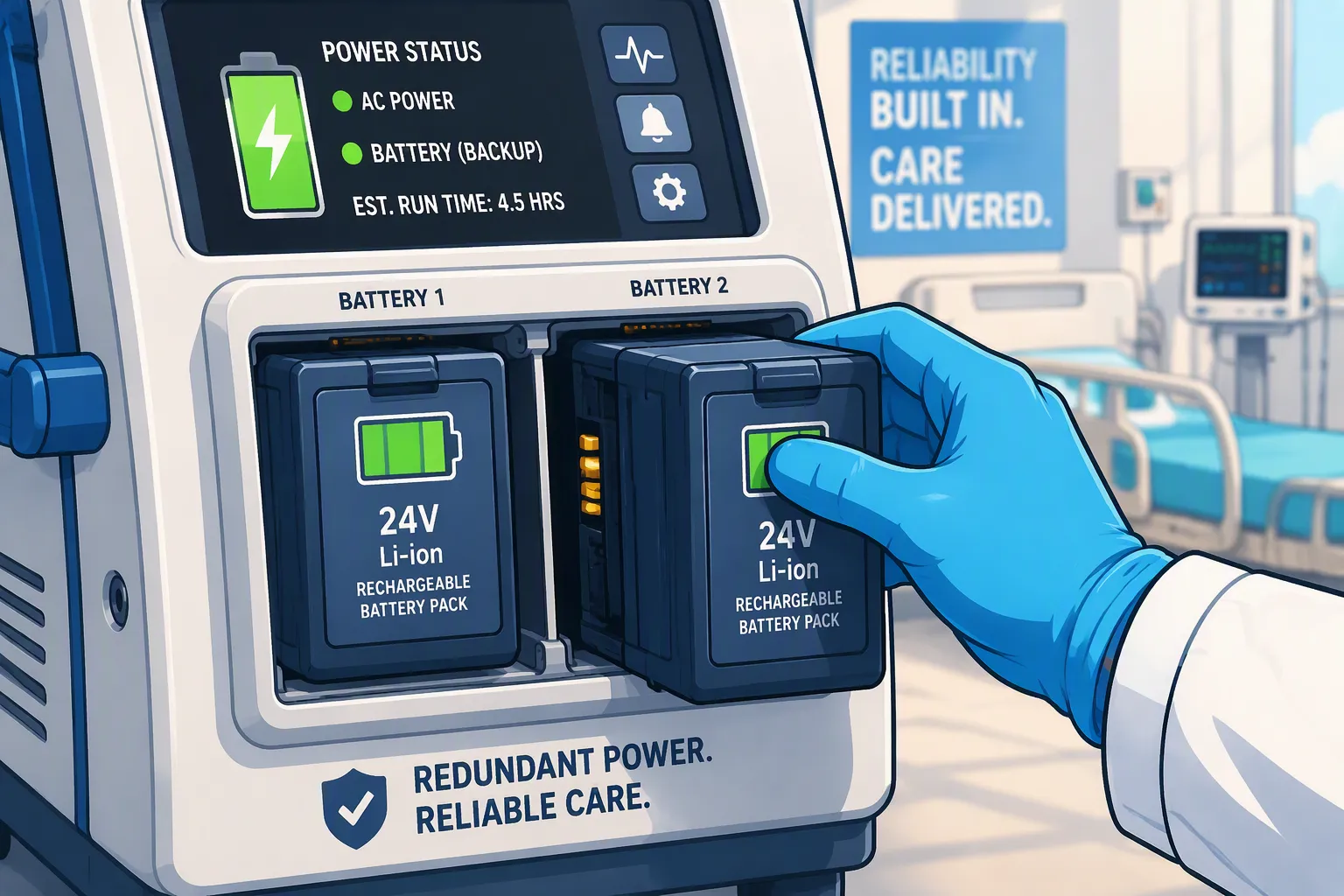
Reliable battery backup helps life-support medical devices maintain essential functions during mains interruptions, patient transport, and battery replacement. However, adding a second battery does not automatically eliminate power-system failures. Shared connectors, charging circuits, control electronics, or power converters can still interrupt both supply paths.
A redundant battery architecture must address the failures identified in the device’s risk analysis. Each available power path needs sufficient output capability, appropriate fault isolation, and verified transition behavior. Engineers must also consider whether the remaining battery can support the required operating time under low-temperature and aged-battery conditions.
For medical battery solutions, the design starts with the device’s essential performance and power requirements. Battery count, chemistry, hot-swap capability, and monitoring functions should follow those requirements.
Quick Answer: Consider redundant battery paths when a single battery or power-path failure could create unacceptable risk, or when battery replacement must occur without interrupting operation. Verify that the remaining source can support the required load and duration, and assess shared components that could defeat the redundancy.
Key Takeaways
Define the functions and operating duration that must remain available after a power-source failure.
Verify that the remaining battery can support the required load, including startup and transient demand.
Evaluate shared chargers, converters, connectors, firmware, and thermal conditions for common-cause failures.
Coordinate the Battery Management System (BMS) with power-path protection, source selection, and device alarms.
Validate battery removal, fault isolation, and source transitions in the complete device using representative operating conditions.
Part1: When Does a Medical Device Need Battery Redundancy?

Battery redundancy becomes relevant when the loss of a single battery or power path could create an unacceptable risk. The design decision should start with the device’s intended use, essential performance, and required response to a power interruption.
For example, a transport ventilator may need to maintain ventilation while disconnected from mains power. Its power architecture must account for the expected transport duration, operating settings, alarms, and available intervention time. A second battery can improve availability, but only if it remains capable of supporting the required functions when the first source becomes unavailable.
Define three requirements before selecting an architecture:
Power: The continuous and transient load the remaining source must supply.
Energy: The operating duration required after a source failure.
Transition behavior: The voltage disturbance and interruption the device can tolerate.
A pack may have enough energy for the required runtime but insufficient current capability to handle a motor startup. Conversely, it may support peak demand but lack sufficient usable energy after aging or cold exposure.
For medical battery solutions, these requirements should be verified against the complete device. Hospital emergency power, an external UPS, and an internal battery serve different roles. Facility backup does not establish continuity while equipment is unplugged or moving between locations.
Part2: Dual-Pack, N+1 and 2N Architectures
Two battery packs can provide additional runtime, redundancy, or both. The distinction depends on what the system can do after one pack becomes unavailable.
Architecture | Operating Principle | Key Design Question |
|---|---|---|
Dual-pack capacity expansion | Both packs contribute to the required power or runtime | Can the remaining pack meet the defined requirements alone? |
N+1 | One additional supply unit is provided beyond the N units needed for the specified load | Can the system tolerate the loss of any one unit? |
2N | Two complete supply sets are provided, each capable of meeting the specified requirements | Are the paths sufficiently independent within the defined architecture boundary? |
If a device needs both packs to support its maximum load, losing either pack may require reduced functionality or shutdown. That arrangement should not be described as fully redundant for maximum-load operation.
Likewise, a dual-pack system might maintain operation after one pack fails but provide a shorter backup duration. Document that duration explicitly rather than implying that full runtime remains available.
2.1 Identify Shared Failure Points
Redundancy must be assessed across the power path, not just at the battery terminals. Shared components may include:
Charging circuits and external adapters
DC/DC converters and power-selection controllers
Connectors, wiring, and the common supply bus
Firmware, communication interfaces, and auxiliary power rails
A fault in a shared component can affect both packs. Physical proximity can also expose both packs to the same liquid ingress, impact, or thermal event.
Use the risk analysis to determine which failures require isolation, independent protection, monitoring, or another control. The presence of two batteries alone does not demonstrate adequate fault tolerance.
Part3: Power-Path Isolation and Hot-Swap Control
A hot-swappable design allows a battery to be removed and replaced while another qualified source supports the device. Successful operation requires control of both the electrical transition and the replacement process.
Ideal-diode circuits and power multiplexers can manage source selection and limit reverse current between sources. However, reverse-current blocking does not provide complete isolation from every electrical fault. Evaluate shorted switching devices, common-bus faults, and loss of controller power separately.
3.1 Control Battery Insertion and Removal
When a replacement pack is inserted, voltage differences can produce inrush current into the device’s input capacitance or another connected source. The design may require controlled switching, precharge, or current limiting.
Do not directly connect packs with different terminal voltages unless the architecture is designed to manage the resulting current.
Before permitting removal, the device should determine whether the remaining source can support the required load. Depending on the intended workflow, the interface may indicate which pack can be removed and warn when backup capacity is unavailable.
3.2 Validate the Supply Rail During Transitions
There is no universal switching-time target that establishes acceptable hot-swap performance. Evaluate the voltage at the powered circuits and confirm that the device stays within its defined performance limits.
Useful validation conditions include:
Test Condition | What to Verify |
|---|---|
Battery removal at maximum expected load | Supply voltage remains within the permitted range |
Remaining pack at low state of charge | Available power and runtime meet the defined reserve |
Aged remaining pack | Increased resistance does not cause an unacceptable voltage drop |
Replacement pack insertion | Inrush and reverse current remain within component limits |
Battery protection shutdown | The alternate source responds as intended |
Communication loss during replacement | Local protection and defined fallback behavior remain available |
Hold-up capacitors or supercapacitors may help support short transitions. Their selection depends on the load, allowable voltage drop, ESR, temperature, and aging. They supplement the power-path design; they do not make it immune to failure.
Part4: Cell Selection, BMS and Thermal Protection
Cell chemistry should follow the device’s power, runtime, size, and service requirements. LiFePO4 can offer favorable thermal stability and cycle life, while NMC can offer higher energy density for portable equipment. Compare specific cell models under relevant conditions rather than relying on chemistry-wide safety rankings.
For custom lithium battery packs, assess usable energy and peak-current capability at the expected end of service life. A new pack’s room-temperature capacity is insufficient evidence for backup performance throughout the device’s life.
4.1 Define Pack Protection and System Control Separately
The Battery Management System (BMS) monitors cell conditions and implements the pack’s protection functions. The device’s power controller manages source selection, load support, and charging coordination. These functions may be integrated, but their responsibilities should remain explicit.
Cell balancing reduces imbalance between series-connected cells. Passive balancing dissipates energy from selected cells, while active balancing transfers energy. Neither method repairs a degraded cell or guarantees equal usable capacity.
State of charge and state of health are estimates. Their uncertainty should inform reserve calculations and low-battery warnings, particularly when packs differ in age, temperature, or usage history.
Local protection should remain effective if host communication fails. The device should detect stale or missing battery data and respond according to its defined operating requirements.
4.2 Coordinate Charging With the Available Power Budget
Simultaneous charging is possible when the supply and charging circuits support it. Sequential charging may be appropriate where input power or thermal capacity is limited.
The controller should allocate power among device operation, battery charging, and auxiliary loads. Validate transitions when mains power is removed, a pack is inserted, or charging demand changes.
Protection settings must also accommodate normal device transients without permitting operation outside the cells’ and components’ approved limits.
4.3 Address Electrical and Thermal Faults
Disconnecting a pack from the load does not necessarily stop an internal cell short circuit. Electrical protection therefore needs to be considered alongside cell selection, mechanical protection, and thermal design.
Evaluate heat transfer between packs, enclosure conditions, sensor placement, and potential fault propagation. Fans or liquid cooling are application-dependent choices, not standard requirements for every medical battery system.
Electronic protection switches and conventional fuses serve different functions. Their coordination should account for fault current, interruption capability, response time, and possible failure modes. Automatic restart after a fault should be enabled only where the recovery behavior has been evaluated.
Part5: System Validation and Risk Management
IEC 60601-1 addresses basic safety and essential performance of medical electrical equipment. Applicable collateral and device-specific standards may introduce further requirements. ISO 14971 provides the risk-management process used to identify hazards, evaluate risks, implement controls, and assess their effectiveness.
A redundant topology is one possible risk control. Its effectiveness must be demonstrated within the complete device; the designation “2N” does not establish compliance.
5.1 Translate Failure Scenarios Into Tests
Start with the failures identified in the risk analysis and define measurable acceptance criteria.
Failure Scenario | Example Acceptance Criteria |
|---|---|
Loss of mains power | Required functions continue within defined limits |
One battery becomes unavailable | Remaining source supports the specified load and duration |
Backup battery is degraded or disconnected | The device identifies the unavailable reserve and provides the required indication |
Pack communication fails | Invalid data is detected and the defined fallback response occurs |
Battery insertion causes a transient | No unacceptable reset, voltage excursion, or interruption occurs |
A shared power-path component fails | The resulting behavior satisfies the applicable risk-control requirements |
Fault testing should be performed using controlled methods appropriate to the failure being evaluated. Physically creating an internal cell short is not a routine substitute for a planned system-level fault simulation.
5.2 Include Aging and Environmental Conditions
Test representative operating profiles, including the highest expected continuous demand and relevant load transients. Include low state of charge, aged packs, and the specified operating temperature range.
Verify the required backup duration after one source becomes unavailable. Also assess alarm timing and whether sufficient energy remains for the intended response.
Record the hardware, firmware, cell model, pack configuration, test conditions, and acceptance criteria. Changes that affect power consumption or source management should undergo an impact assessment to determine the necessary revalidation.
5.3 Maintain Traceable Production Records
Use pack identifiers and controlled records to connect the product with relevant component lots, firmware versions, and test results. The storage method should support the quality system and service workflow.
Cloud storage and on-pack memory are possible implementations, but neither is a universal requirement. The objective is reliable retrieval of the information needed for investigation, service, and corrective action.
Part6: Backup Readiness and Maintenance
A backup battery provides limited benefit if its deterioration remains unnoticed until the primary source fails. Readiness monitoring should establish whether the reserve is connected, charged, and capable of meeting its assigned role.
Voltage alone does not establish remaining capacity or power capability. Use validated battery estimates, diagnostics, and periodic performance checks appropriate to the device.
6.1 Set Replacement Criteria Around Device Requirements
Replacement criteria should account for usable runtime, voltage sag under load, abnormal temperature, physical damage, and diagnostic faults. A single cycle-count threshold may not adequately represent a standby battery’s condition.
Follow the device manufacturer’s approved charging and storage instructions. Equipment designed to remain connected to mains power may require a different maintenance strategy from removable packs held in storage.
Hot-swapping can support extended operation when charged replacements are available, but the workflow must account for replacement errors, insufficient reserve, and connector wear.
6.2 Use Diagnostics to Support Service Decisions
Local BMS estimates and recorded operating data can help identify declining performance. Predictive analytics may provide additional information, but they do not guarantee detection of every future failure.
Essential protection and required alarms should remain available without a cloud connection. Maintenance decisions should combine diagnostic evidence with validated service criteria and the device’s intended use.
An effective redundant battery design demonstrates what happens when a source fails, how long the remaining source can support the device, and how loss of reserve is communicated to the operator. Those verified behaviors provide the basis for dependable backup operation.
FAQ
What is the difference between N+1 and 2N redundancy?
N represents the capacity or number of supply units required to support the specified load. N+1 adds one additional unit so that the system can tolerate the loss of one unit, provided the remaining units meet the operating requirements.
2N provides two complete supply sets, each capable of supporting the specified load independently. For battery systems, that capability must include both power and the required backup duration.
Neither label guarantees complete fault isolation. Define the architecture boundary and identify any shared components.
Does using two battery packs make a medical device redundant?
Only if the system can tolerate the relevant failure of either pack while maintaining the required functions. Two packs that must both operate to supply the load provide additional capacity, but may not provide redundancy.
A shared converter, connector, or control circuit can also remain a single point of failure. Electrical isolation between battery paths does not, by itself, prevent thermal propagation between adjacent packs.
Should you choose LiFePO4 or NMC for redundant medical battery packs?
Compare the exact cells against the device’s runtime, peak current, weight, volume, charging, and service-life requirements. LiFePO4 can offer favorable thermal stability and cycle life, while NMC can provide higher energy density for compact equipment.
Neither chemistry establishes system safety on its own. Cell quality, pack construction, protection, thermal design, and complete-device validation remain necessary. Avoid comparing generic decomposition temperatures as though they were permissible operating limits.
How does hot-swapping work in a redundant battery system?
During battery removal, another qualified source supplies the device through a controlled power path. Ideal-diode circuits or power multiplexers can manage source selection and limit reverse current, while additional circuitry may be needed for inrush control and fault isolation.
Hot-swap performance depends on the complete design. Validate supply-rail droop, transition time, peak load capability, and device behavior during removal and insertion. There is no universal switching-time specification that guarantees uninterrupted operation.
Which standards apply to redundant medical battery designs?
IEC 60601-1 addresses basic safety and essential performance of medical electrical equipment. Applicable collateral and device-specific standards may introduce additional requirements. ISO 14971 provides the framework for identifying hazards, evaluating risks, and implementing risk controls.
Selecting a 2N topology does not automatically demonstrate compliance. Document the relevant failure scenarios, architecture decisions, and verification evidence for the intended device and target market.
How should you test a redundant battery architecture?
Test the complete device during mains loss, battery removal, and representative battery or power-path faults. Confirm that the remaining source supports the required functions without unacceptable voltage droop, resets, or loss of alarms.
Include aged batteries, low state of charge, temperature extremes within the specified operating range, and maximum expected load. Evaluate communication loss, sensor faults, charger faults, and failures in shared components where relevant to the risk analysis.
How do you verify that the backup battery is ready?
Monitor each pack’s availability, temperature, state of charge, and health, and use validated checks to detect a disconnected or degraded backup source. Define a warning or operating restriction when the required reserve is unavailable.
Maintenance should verify usable capacity and power capability against the device’s service criteria. A second battery provides limited protection if its degradation remains undetected until the primary source fails.


