

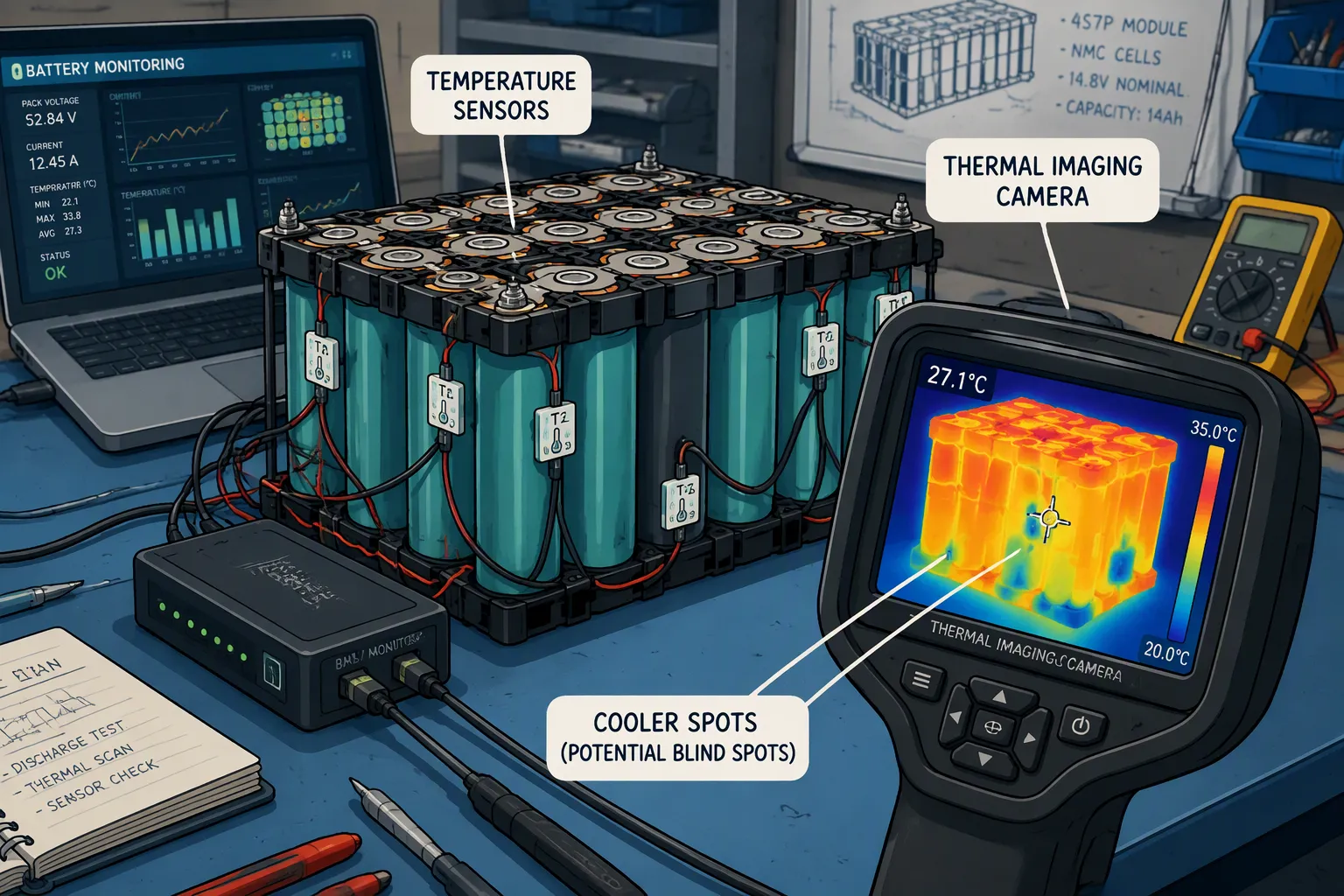
Temperature sensors are a primary input to the battery management system, but sensor count alone does not guarantee protection. A pack can contain several thermistors and still miss a hot interconnect, a poorly cooled interior cell, or a sensor that has become thermally coupled to the enclosure instead of the cell. Effective placement begins with a thermal-risk map and ends with validation under the pack’s real electrical, mechanical, and environmental conditions.
Quick Answer: Place temperature sensors where credible faults and normal operation create the highest temperature or fastest temperature rise. Cover representative cells, current-carrying joints, thermally disadvantaged regions, coolant inlet and outlet conditions, and ambient or enclosure temperature where relevant. Determine the final number and alarm thresholds through simulation, thermal mapping, tolerance analysis, and fault testing rather than a fixed cells-per-sensor rule.
Key Takeaways
Map heat generation and heat rejection before selecting sensor locations.
Monitor both cell temperature and non-cell hotspots such as busbar joints, contactors, fuses, and high-current connectors.
Choose representative hot and cold locations instead of spacing sensors uniformly.
Account for sensor response time, mounting pressure, adhesive, insulation, wiring faults, and manufacturing tolerances.
Validate the complete sensing chain, including the sensor, harness, analog front end, BMS software, thresholds, and shutdown response.
Part 1: Build a Thermal-Risk Map First
1.1 Where Heat Comes From
Cells generate heat through ohmic losses, electrochemical polarization, and reversible entropic effects. The dominant contribution changes with current, state of charge, temperature, chemistry, and cell age. Pack components create additional heat: contact resistance at welded or bolted joints, conductor resistance in busbars, switching losses in MOSFETs and contactors, and losses in fuses, connectors, and cables.
Because heat generation scales strongly with current, high-power events can expose problems that remain invisible during a low-rate bench test. A slightly resistive joint may stay cool at 0.2C and overheat during a pulse load. Sensor placement therefore has to reflect the worst credible load profile, not only nominal operation.
1.2 Where Heat Accumulates
The hottest cell is not always the cell with the highest current density at its terminal. In an air-cooled module, interior cells or downstream cells may be hottest. In a liquid-cooled module, the warmest region may be near the coolant outlet or at a location with poor cold-plate contact. In a sealed pack, structural ribs, foam, potting, and restricted air spaces can create local thermal bottlenecks.
Use thermal simulation and instrumented prototypes to identify the locations with the highest absolute temperature, the greatest cell-to-cell gradient, and the fastest rate of rise. Those three conditions may occur at different points and may require different sensors or thresholds.
Part 2: Common Thermal Monitoring Blind Spots
2.1 Interconnects and High-Current Components
A cell-surface sensor may not detect a loose terminal, cracked weld, corroded connector, or degraded contactor quickly enough. These faults create localized resistive heating while adjacent cells remain within their normal temperature range. Packs with high continuous current, frequent pulses, vibration, or field-serviceable connections should include direct or closely coupled monitoring at the most critical joints.
Candidate locations include main positive and negative terminals, series busbar transitions, fuse elements, contactors, charge and discharge connectors, and joints identified by voltage-drop or resistance analysis. Temperature data can also be combined with current and connector voltage-drop trends to improve fault discrimination.
2.2 Thermally Disadvantaged Cells
Uniform sensor spacing can leave the worst location unmonitored. The most thermally disadvantaged cell may be at the module center, the end of an airflow path, the coolant outlet, an enclosure corner, or beside an insulating structural feature. A sensor placed on a convenient outer cell can under-report the temperature of an interior cell by a meaningful margin.
Mounting a sensor on an end plate, cold plate, or module frame measures that structure unless the thermal path to the target cell is characterized. Contact resistance and thermal mass introduce delay and attenuation. The BMS may therefore see a safe value while the cell is heating rapidly.
2.3 Sensor and Harness Failures
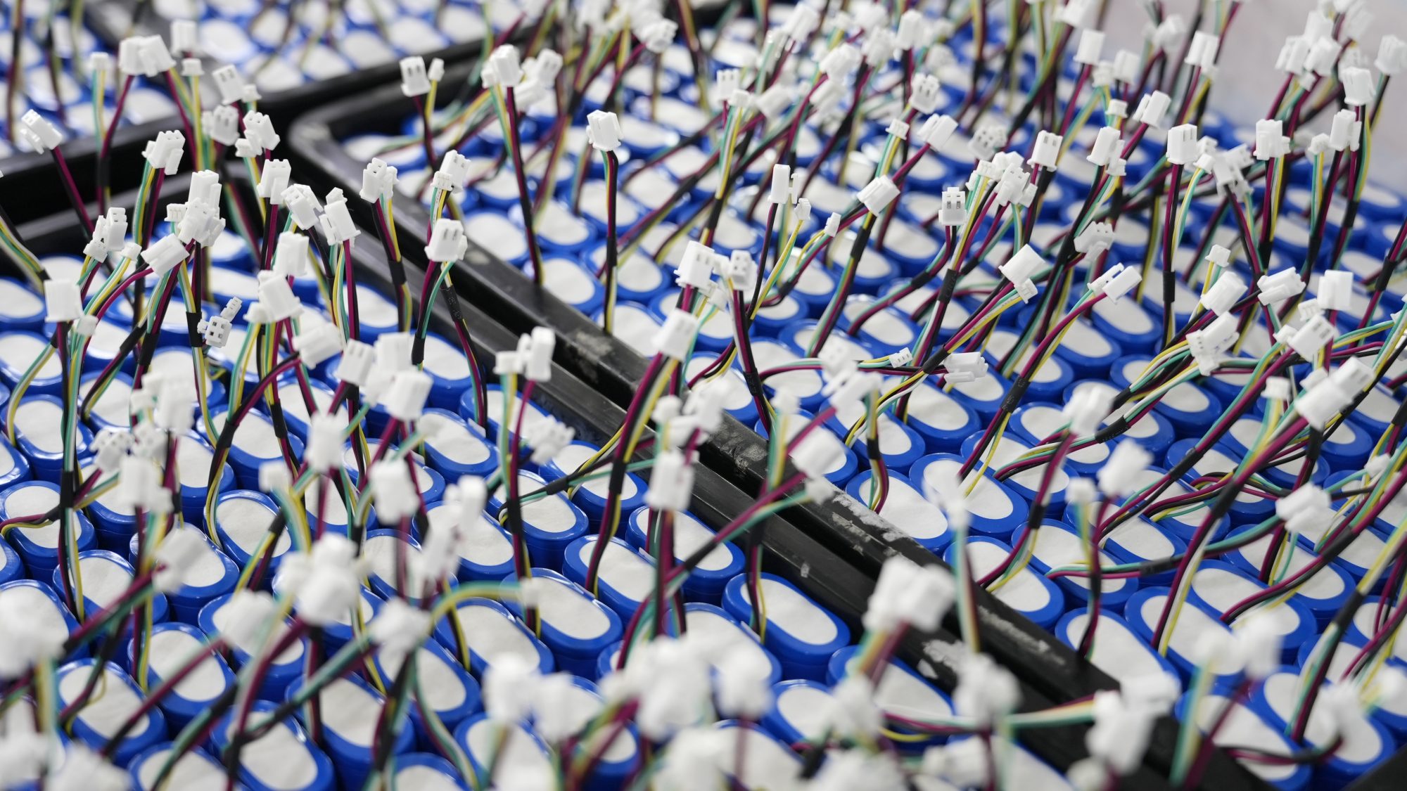
A monitoring system also has blind spots when a sensor lifts from the surface, adhesive creeps, a lead breaks, a connector frets, or electrical noise corrupts the signal. Design diagnostics for open circuit, short circuit, implausible temperature, excessive rate of change, and disagreement between neighboring channels. A fixed substitute value should never be allowed to look like a valid reading without a fault flag.
Part 3: Placement by Cell Format and Cooling Architecture
3.1 Cylindrical, Prismatic, and Pouch Cells
Cell or Pack Feature | Useful Sensor Locations | Main Validation Question |
|---|---|---|
Cylindrical cell group | Representative interior and boundary cells; downstream airflow or coolant regions | Does the selected cell track the hottest cell across load and ambient conditions? |
Prismatic cell | Surface locations identified by thermal mapping; terminal region when connection heating is credible | Does casing temperature provide adequate warning of internal or terminal heating? |
Pouch cell | Broad-face hotspot identified by testing; tab region; mechanically constrained regions | Does the sensor remain coupled through swelling, cycling, and compression changes? |
Busbar or connector | Near the highest-resistance joint without compromising insulation clearance | Can the sensor detect a degraded joint before damage propagates? |
Liquid-cooled module | Representative cells near inlet and outlet, plus poor-contact locations | Can the system detect flow loss, blockage, or cold-plate interface variation? |
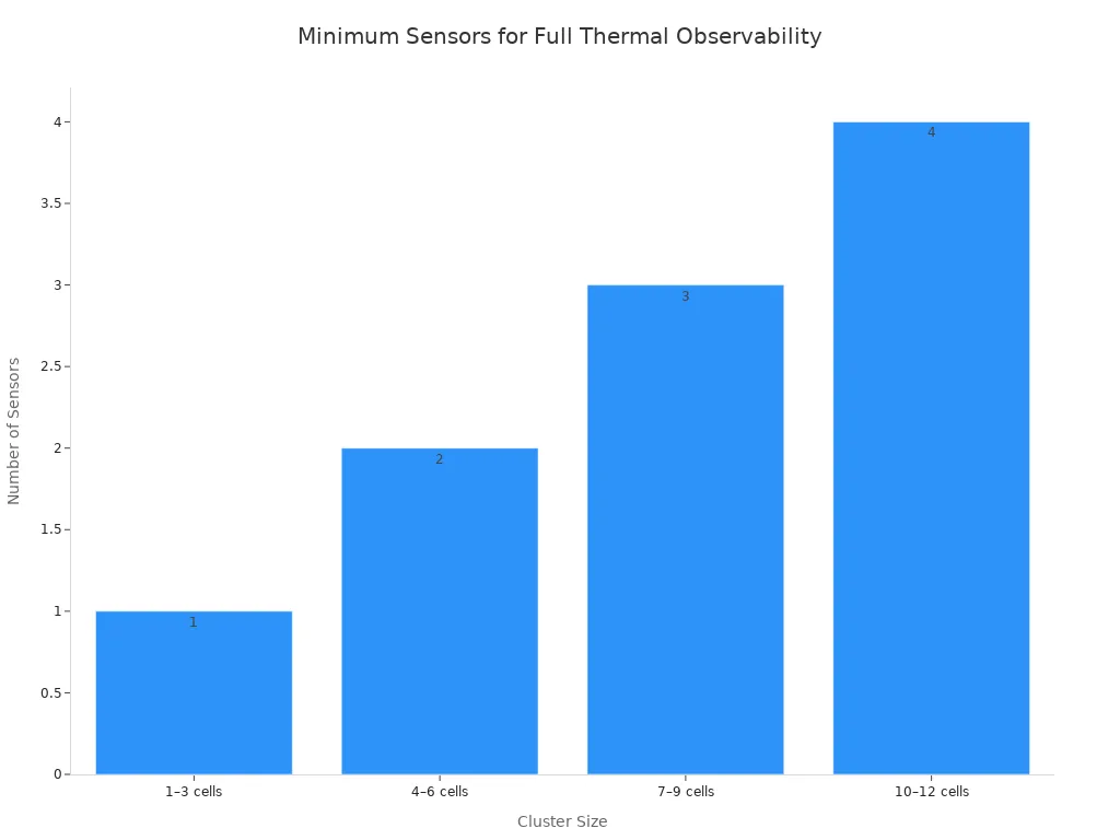
There is no universal rule that every three cells require one sensor. The minimum channel count depends on thermal coupling, cell geometry, cooling design, current profile, fault containment strategy, required diagnostic coverage, and the accuracy of any estimation model. A rule derived for one cylindrical-cell string should not be transferred automatically to a prismatic or pouch module.
3.2 Pack-Level Coverage
At pack level, allocate channels to representative cell zones, current-carrying hardware, cooling-system boundaries, and ambient conditions. Packs with parallel modules may need comparable coverage in each branch so that a local cooling or connection fault is not hidden by a normal average elsewhere.
The BMS and PCM architecture must support the required measurement range, channel accuracy, filtering, diagnostics, and reaction time. If channels are multiplexed, confirm that the sampling interval is fast enough for the quickest credible thermal event.
Part 4: Sensor Selection and Installation
4.1 NTCs, RTDs, and Thermocouples
NTC thermistors are common in production battery packs because they are compact, responsive, and economical. RTDs offer good stability and linearity but typically require more signal-conditioning consideration. Thermocouples cover a wide range and are useful during development testing, although cold-junction compensation and low-level signal handling make them less common for routine embedded cell monitoring.
Select the technology from the required temperature range, accuracy, response time, long-term drift, isolation, package, harness length, and BMS input design. Published sensor accuracy is only one part of the error budget; mounting and thermal lag can create a larger error than the sensor element itself.
4.2 Mounting and Thermal Coupling
The sensor must maintain repeatable contact without damaging cell insulation or creating a conductive path. Define the adhesive, tape, clip, insulation layer, contact pressure, cure process, and allowable placement tolerance. Test adhesion after thermal cycling, humidity, vibration, and cell dimensional change.
A thick adhesive bead or foam layer can slow response. A sensor touching both a hot cell and a cool structural member may report a blended temperature. Verify response time in the final assembly, not only in free air. For serviceable packs, make replacement procedures and sensor routing unambiguous.
4.3 Wiring and Signal Integrity
Route low-level sensor wiring away from high-current conductors, switching nodes, and noisy communication lines. Use appropriate pair routing, filtering, shielding, strain relief, and isolation. Confirm readings during maximum charge and discharge current, contactor switching, charger operation, and electromagnetic immunity testing.
For long harnesses, include lead resistance and connector resistance in the measurement error analysis. The BMS should distinguish an actual thermal event from a harness fault and move the system to a defined safe state when temperature information is unreliable.
Part 5: Validate Placement and Protection Logic
5.1 Simulation and Instrumented Prototype Testing
Use simulation to identify likely gradients, then verify them with a heavily instrumented prototype. Development instrumentation can include more thermocouples than the production design, thermal imaging where line of sight is available, coolant measurements, and voltage-drop measurements across critical joints.
Test normal operation and credible faults at the boundaries of state of charge, ambient temperature, current, airflow or coolant flow, manufacturing tolerance, and aging. Include blocked airflow, reduced pump performance, poor thermal-interface contact, resistive joints, failed sensors, and disconnected harnesses where these are credible hazards.
5.2 Thresholds, Rate-of-Rise, and System Response
Absolute overtemperature limits alone may react too late. Consider rate-of-rise limits, temperature differences between comparable cells or modules, and disagreement between a component sensor and nearby cell sensors. Thresholds must account for measurement uncertainty and thermal lag while avoiding nuisance trips.
Verify the complete response: warning, current derating, charge or discharge cutoff, contactor opening, alarm communication, event logging, and recovery behavior. Functional safety and product standards should be selected for the actual application. For medical, robotics, security, infrastructure, and industrial products, the safety case must connect each credible thermal fault to a verified control or protective response.
Conclusion
Reliable temperature monitoring is a system-design task, not a thermistor-count exercise. Map where heat is generated, where it accumulates, and how faults develop; then place sensors at representative and safety-critical locations. Validate the mechanical mounting, signal chain, diagnostics, thresholds, and BMS response in the complete battery pack. Large Power can support custom lithium battery solutions with application-specific thermal sensing, BMS design, enclosure integration, and validation requirements.
FAQ
Where should a temperature sensor be placed on a lithium battery cell?
Place it at the surface location shown by thermal mapping to represent the highest-risk cell temperature. Depending on cell format and cooling, that may be near a terminal, on a broad face, at an interior-cell surface, or near a coolant outlet. Do not apply one location to every design.
How many temperature sensors does a battery module need?
There is no universal cells-per-sensor ratio. Determine the count from thermal gradients, cooling architecture, cell format, current profile, fault coverage, BMS channel capability, and validation results.
Should busbars and connectors have dedicated sensors?
Use dedicated or closely coupled monitoring when joint heating is a credible hazard and nearby cell sensors cannot detect it quickly enough. High-current, high-vibration, or serviceable connections deserve particular attention.
Can a sensor mounted on an end plate represent cell temperature?
Only if testing shows that the plate reading tracks the target cell with acceptable error and response time across the full operating range. Thermal-interface resistance can delay and reduce the measured temperature rise.
How should the BMS detect a failed temperature sensor?
Monitor for open and short circuits, implausible values, unrealistic rate of change, and disagreement with related channels. Define a safe response when temperature data is missing or unreliable.


