

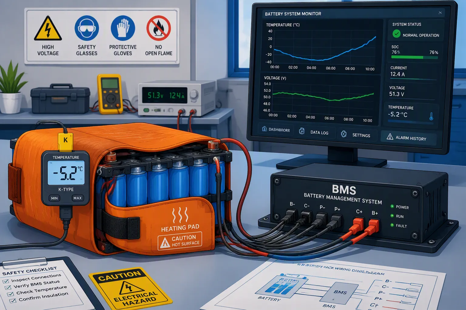
Cold-weather charging presents a design challenge for lithium-ion battery packs used in outdoor equipment, robotics, and remote monitoring systems. Low cell temperatures slow electrochemical reactions and can increase the risk of lithium plating during charging. The risk depends on cell design, temperature, charging current, state of charge, and aging.
Effective protection starts with a validated charging envelope. A Battery Management System (BMS) should restrict or stop charging when measured cell temperatures fall outside the approved limits. Where charging must remain available in cold environments, a controlled heating system can bring the cells into their permitted charging range before charging resumes.
For custom lithium battery packs, reliable operation depends on sensor placement, temperature gradients, charger coordination, and fault handling. A warm enclosure or heater surface does not necessarily mean every cell is ready to charge.
Quick Answer: Set charging limits from the selected cell’s specifications and pack-level validation. Inhibit charging below the approved minimum temperature, use controlled heating when required, and resume charging only after relevant cell-temperature measurements satisfy the restart conditions. Include hysteresis and sensor-fault handling to prevent unstable or unsafe operation.
Key Takeaways
Define charging temperature and current limits for the exact cell model. Chemistry names alone do not establish safe operating limits.
Treat low-temperature charging cutoff as a core protection function. Add heating where the application requires cold-weather charging availability.
Position sensors to detect cold cells and heater hot spots, accounting for measurement error and thermal lag.
Separate charge-disable and charge-restart conditions with validated hysteresis to avoid repeated switching near the threshold.
Validate heater operation, charger behavior, sensor failures, and temperature distribution in the complete battery pack.
Part 1: Risks of Low-Temperature Charging
You can discharge lithium battery packs at temperatures as low as -40°C without catastrophic damage. Charging them below 0°C presents an entirely different danger. The difference lies in the electrochemical processes occurring at the anode. Understanding this distinction matters for anyone designing battery systems for cold environments.
1.1 Lithium Plating and Capacity Loss
Low temperatures slow lithium-ion diffusion into the graphite anode. Reduced ionic mobility and sluggish electrode kinetics cause this slowdown. The anode potential then drops close to or below the Li/Li+ equilibrium potential (0V vs. Li/Li+). This condition triggers a dangerous sequence:
Lithium ions arrive at the anode surface but cannot intercalate efficiently into the graphite structure.
These excess ions undergo reduction instead of normal insertion.
Metallic lithium deposits form on the anode surface rather than storing energy within the graphite layers.
These deposits accumulate with each cold-charging cycle.
The result is irreversible capacity loss. Each cycle at low temperature permanently removes lithium from the usable inventory of the cell. You cannot recover this lost capacity by warming the battery later. The damage compounds over repeated exposure.
Microscopically, these metallic deposits do not remain as a smooth layer. They grow into dendritic structures with sharp, branching morphologies. These dendrites consume active lithium and degrade the anode structure itself. The graphite lattice suffers mechanical stress as metallic lithium forms and accumulates.
1.2 Safety Hazards and Thermal Runaway
Dendrite growth presents more than a capacity problem. These metallic structures can grow long enough to penetrate the separator membrane. The separator sits between anode and cathode as a physical barrier. Once a dendrite pierces this barrier, it creates an internal short circuit path.
An internal short allows current to flow directly between electrodes without passing through the external circuit. Localized heating occurs at the short point. This heat generation can accelerate exothermic reactions within the cell. Temperatures rise further, triggering electrolyte decomposition and cathode breakdown. The cascade can escalate into thermal runaway.
For B2B applications in medical devices, robotics, and infrastructure systems, thermal runaway represents an unacceptable risk. A single cell failure can propagate to neighboring cells in a pack. The financial and operational consequences extend far beyond replacing one battery.
These risks explain why BMS control strategies must prioritize temperature monitoring during charging. Your protection system needs to recognize cold conditions and respond before plating begins. The next sections examine how cutoff circuits and heating systems implement this protection.
Part 2: Cutoff Charging Strategies
The first line of defense against cold-charging damage is a hard electrical cutoff. Your BMS must physically prevent charging current from reaching cells when temperatures drop below safe operating limits. This strategy requires precise temperature thresholds and reliable disconnection mechanisms.
2.1 Temperature Thresholds and Disconnection
Most lithium-ion chemistries share a common safety boundary: you should not charge below 0°C. This threshold applies to NMC, LCO, and LMO cells. LiFePO4 chemistry offers more flexibility. Manufacturers may set adjustable thresholds for these cells, sometimes allowing charging at slightly lower temperatures with reduced current.
The cutoff point depends on two factors: battery temperature and maximum charge rate. You cannot set a single universal threshold for all applications. A cell charged at 0.5C faces greater plating risk than one charged at 0.1C at the same temperature. Your threshold must account for the actual charge current your system delivers.
Manufacturer datasheets provide specific guidance for low-temperature operation. The table below shows typical maximum charge rates for LiFePO4 cells across cold temperature ranges:
Temperature Range | Max Charge C-Rate (LFP) |
|---|---|
0°C – 5°C | 0.1C – 0.2C |
5°C – 15°C | 0.2C – 0.3C |
-10°C – 0°C | 0.05C or disabled |
Below -10°C | Charging disabled |
These values represent safe operating windows. You should treat them as design constraints, not suggestions. When your system operates between -10°C and 0°C, you may allow a minimal 0.05C charge rate or disable charging entirely. Below -10°C, you must cut off charging completely.
2.2 Implementation in BMS
Your BMS implements these thresholds through temperature sensing and switch control. The system monitors cell temperatures continuously using thermistors or thermocouples placed at critical points within the pack. When any cell falls below the configured cutoff temperature, the BMS opens the charging path.
The disconnection mechanism typically uses MOSFET switches in the charge circuit. These switches respond within milliseconds to temperature readings. You cannot rely on manual intervention or external charger controls. The BMS must act autonomously to protect the pack.
Setting the cutoff threshold requires careful analysis of your specific application. Consider the maximum charge rate your charger delivers. A fast-charging system for robotics may need a higher cutoff threshold than a slow-trickle charger for medical devices. You should also account for temperature gradients across the pack. Cells near the edge may run colder than center cells. Your BMS should use the lowest measured temperature for cutoff decisions.
These BMS control strategies prevent damage before it begins. The system does not wait for voltage anomalies or capacity degradation signs. It responds directly to the root cause: low temperature. This proactive approach protects your battery investment and ensures operational reliability.
For infrastructure systems and industrial equipment operating outdoors, you must configure these thresholds carefully. A medical device in a temperature-controlled hospital room may never trigger the cutoff. A security camera in a northern climate will encounter cold conditions regularly. Your BMS configuration must match your real operating environment.
The cutoff strategy alone cannot solve all cold-weather charging challenges. It prevents damage but also prevents charging. When you need to charge in cold conditions, you require a heating strategy. The next section examines how you can warm cells safely before charging begins.
Part 3: Heating Strategies for Cold Charging
Cutoff protection stops damage but leaves your battery pack unusable in cold conditions. You need a second strategy: controlled heating. This approach raises cell temperature above the safe threshold before charging current flows. You have two main options: internal self-heating and external heating systems.
3.1 Internal Self-Heating and Heaters
Internal self-heating uses the battery’s own current to generate warmth. You apply an alternating current (AC) through the cells. The internal resistance converts this electrical energy into heat. This method distributes warmth evenly throughout the cell core, avoiding hot spots on the surface.
Research demonstrates impressive heating rates with this technique. The table below summarizes results from several published studies:
Study | Heating Rate | Conditions |
|---|---|---|
Hu et al. | 1.67 K/min | AC self-heating, 253.15 K to 278.15 K in 15 min |
Shang et al. | 2.70 K/min | High-frequency AC (45 kHz), 253.1 K to 273.15 K in 7.4 min |
Zhang et al. | 2.33 °C/min | Sinusoidal AC, 7 A (2.25 C-rate), 1 Hz, −15 °C to 5 °C |
Ruan et al. | 3.73 °C/min | Optimal frequency heating, −15.4 °C to 5.6 °C in 338 s |
Qu et al. | 6.86 °C/min | MOSFET pulse heating, switching frequency 0.1–1 Hz |
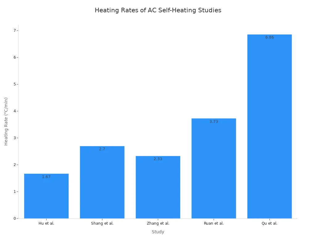
These rates mean you can warm a pack from -20°C to 0°C in roughly 3 to 12 minutes, depending on your chosen method. Faster heating reduces downtime for field equipment. Slower heating places less stress on cell materials.
You can also embed resistive heating elements directly within the battery pack. These thin-film heaters sit between cells or along pack surfaces. They draw power from an external source or from the battery itself at a controlled rate. This approach offers simpler implementation than AC self-heating circuits.
3.2 External Heating and Pre-Charge
External heating applies warmth from outside the cells. Heating pads attached to the pack surface represent the most common approach. You might also use circulating coolant systems that pass warm fluid through channels in the battery housing. These methods work well for large stationary packs in infrastructure applications.
External heating requires careful thermal management. Surface heaters create temperature gradients. The outer cells warm faster than the core cells. You must wait for the entire pack to reach a uniform temperature before charging. Otherwise, you risk charging cells that remain below the safe threshold.
Pre-charge represents a hybrid approach. You apply a very small charging current, typically below 0.05C, while monitoring temperature closely. This trickle current generates mild internal heat without causing significant lithium plating. Once cell temperature rises above 0°C, you switch to normal charging current.
Your BMS control strategies must govern every heating method. The system needs to activate heating only when necessary and deactivate it before overheating occurs. You cannot allow uncontrolled heating to push cell temperatures above safe operating limits. The BMS should also coordinate heating with charging status, ensuring you never apply current while cells remain cold.
For medical devices and robotics applications, you need reliable heating that operates within strict time constraints. A surgical robot cannot wait thirty minutes for battery warm-up. Your heating strategy must match your operational requirements. Consider both the heating rate and the energy cost when selecting your approach.
Part 4: BMS Control Strategies for Protection
Your BMS control strategies must coordinate temperature sensing, decision-making, and action execution. The system reads real-time cell temperatures, compares them against configurable thresholds, and decides whether to cut off charging, activate heating, or allow normal operation. This decision loop runs continuously during every charging session.
4.1 Sensing and Control Algorithms
Temperature sensing forms the foundation of your protection system. You need accurate readings at the cell level, not just pack-level averages. Sensor placement matters significantly. You should position thermistors at the coldest expected points within the pack, typically near edge cells or cooling vents.
Sensor accuracy becomes critical near the 0°C cutoff boundary. Standard sensors rated at 25°C can drift substantially at cold temperatures. You need sensors that maintain accuracy across your full operating range. The table below shows the accuracy requirements for reliable low-temperature cutoff:
Temperature Range | Accuracy Requirement |
|---|---|
-30°C to +10°C | ≤±1.0°C |
Near 0°C (32°F) | ≤±0.5°C |
Relying on 25°C specifications can lead to errors exceeding ±3°C at -20°C. This error margin makes low-temperature cutoff unsafe. A sensor reading -2°C when the actual temperature is +1°C could allow charging below the safe threshold. You must select sensors rated for cold accuracy.
Your control algorithm processes these temperature inputs. Advanced systems use adaptive fuzzy control to handle the nonlinear relationship between temperature, charge rate, and plating risk. These algorithms adjust their behavior based on multiple inputs: cell temperature, temperature trend, charge current, and cell voltage. The system learns from historical data to predict how quickly cells warm or cool.
Simple threshold-based control works for basic applications. The BMS compares the lowest cell temperature against your configured cutoff point. If temperature falls below the threshold, the system opens the charge path. If temperature rises above the heating activation point, the system enables the heater circuit. This straightforward approach suits applications with stable thermal environments.
4.2 Communication and Reporting
Your BMS must communicate its decisions to external systems. The charger needs to know when charging is permitted or blocked. Your host controller requires status updates for operational planning. This communication prevents conflicts between the BMS and other system components.
Standard communication interfaces include CAN bus, RS-485, and I2C. CAN bus works well for robotics and automotive applications. RS-485 suits industrial infrastructure with longer cable runs. Your choice depends on your existing system architecture and data requirements.
The BMS should report several key parameters: pack temperature, charge status, cutoff events, and heating activity. This data helps you diagnose issues and optimize your BMS control strategies over time. You can identify patterns, such as frequent heating activation during certain ambient conditions, and adjust your thresholds accordingly.
Configurable thresholds remain essential for different lithium chemistries. LiFePO4 cells tolerate slightly lower charging temperatures than NMC or LCO cells. Your BMS must allow chemistry-specific configuration. A medical device manufacturer using LiFePO4 cells needs different settings than a robotics company using NMC cells. Your BMS design should support these variations through software configuration rather than hardware changes.
Cutoff protection stops charging when cells fall below safe temperatures. Heating systems raise cell temperature to enable charging in borderline conditions. Your BMS control strategies coordinate both actions seamlessly.
Select a BMS with configurable low-temperature thresholds. LiFePO4 cells tolerate different limits than NMC or LCO chemistries. Your protection settings must match your specific cell chemistry and application environment.
Evaluate your current BMS design against these cold-weather requirements. Medical devices, robotics, and infrastructure systems demand reliable low-temperature performance. Contact our team for advanced BMS solutions tailored to your cold-weather applications.
FAQ
Can you charge a lithium-ion battery below 0°C at a very low current?
Only when the selected cell manufacturer explicitly permits it under specified conditions. Some cells support reduced-current charging below freezing, while others prohibit it. A low charging current alone does not establish safety.
Use the approved temperature-current limits and validate them in the complete pack. Do not apply a universal 0.05C allowance or −10°C cutoff across different cell models.
What happens if a BMS temperature sensor reads incorrectly?
A sensor that reads warmer than the actual cell can allow charging prematurely. For example, a reading of +1°C when the cell is actually −2°C could incorrectly satisfy a 0°C charging threshold.
Account for the complete measurement chain, including sensor tolerance, electronics, placement, and thermal lag. Detect disconnected or shorted sensors, and define a safe response when temperature readings are invalid. Sensor accuracy alone cannot compensate for poor placement.
How long does a cold battery pack take to warm before charging?
Heating time depends on pack mass, starting temperature, heater power, insulation, ambient conditions, and heat distribution. A heating rate demonstrated on one cell or prototype should not be applied directly to another pack.
Measure warm-up time under the intended operating conditions. Resume charging based on validated cell-temperature criteria, rather than a fixed timer or heater-surface temperature alone.
Do LiFePO4 and NMC cells have different low-temperature charging limits?
They can, but the limits depend on the specific cell design. LiFePO4 and NMC cells commonly use graphite-based anodes, which can be vulnerable to lithium plating during cold charging.
LiFePO4’s thermal stability does not automatically give it a lower permitted charging temperature. Compare the manufacturers’ charging specifications and any current restrictions across the required temperature range.
Can lithium-ion batteries discharge safely at low temperatures?
Discharging is often permitted at lower temperatures than charging, but it still has limits. Cold conditions can reduce usable capacity, increase voltage sag, and restrict available power.
Operation at −40°C requires cells and a complete pack specifically rated and validated for that condition. Set discharge current and voltage limits accordingly, and keep cold-charging protection active when the equipment is connected to a charger.
How should the BMS coordinate heating and charging?
Below the approved charging temperature, the BMS should inhibit cell charging and enable heating only when the heating system’s operating conditions are satisfied. Charging can resume when the monitored cell temperatures meet the validated restart criteria.
The design should also address heater overheating, sensor faults, excessive warm-up time, and insufficient available energy. If the battery powers its own heater, its discharge limits and remaining energy must also be considered.


