

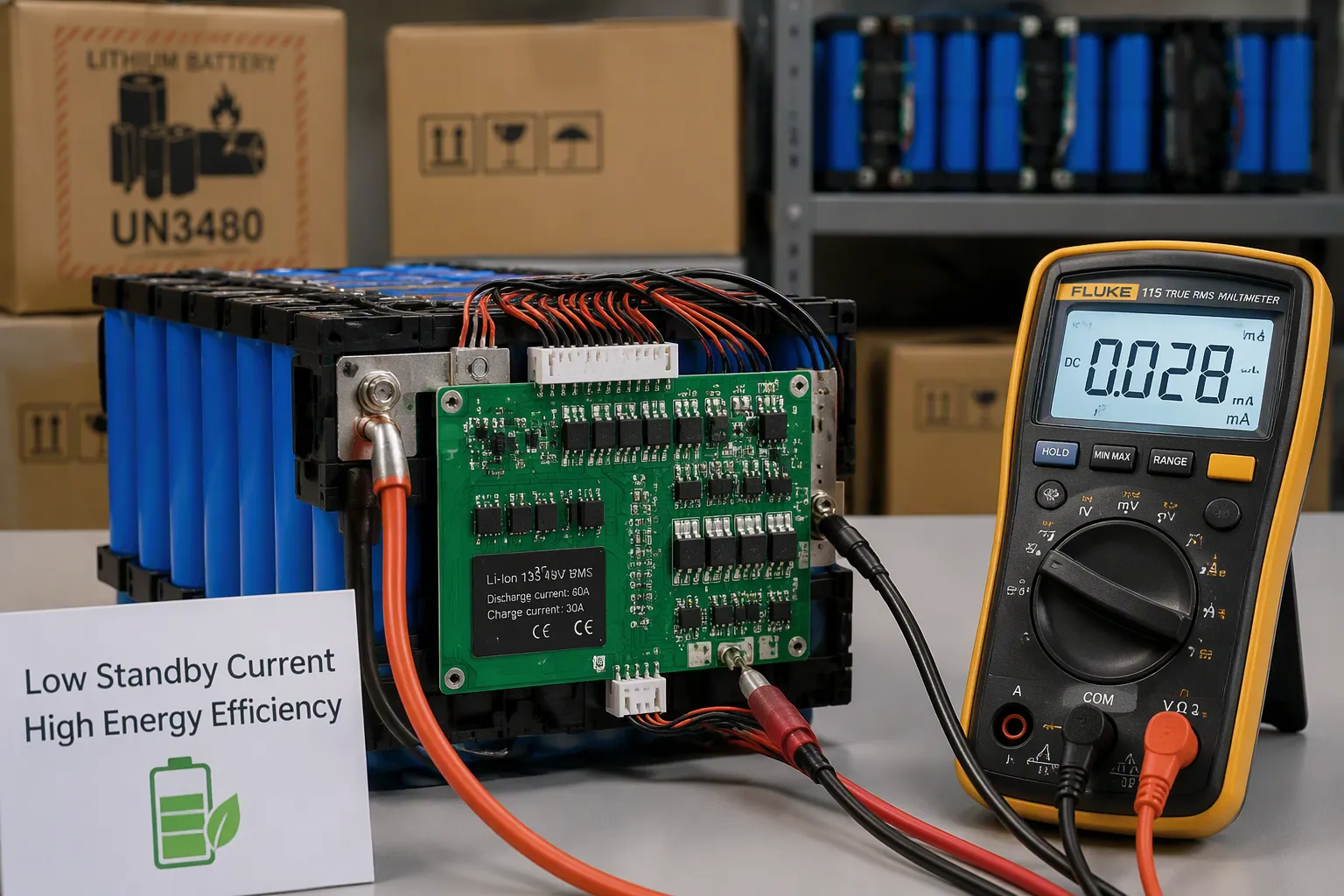
A host device can be switched off while its battery electronics still consume energy. The BMS, gauge, wake circuitry and host backfeed paths can reduce available capacity during storage and shipment. Specify and measure the complete assembly in each operating mode rather than applying an IC quiescent-current figure to the whole pack.
You need three strategies: define operating modes and build a mode-based power budget, count electronic drain separately from cell self-discharge, and check the whole power architecture at the system level.
Quick Answer: Low battery standby current comes from clear mode definitions, tested sleep and ship-mode behavior, measured drain of the whole assembly, and backup energy sized with margin—not from one low-power component.
This guide is for OEM/ODM engineers, plus purchasing and quality teams who specify custom packs.
Key Takeaways
Define operating modes and their acceptance limits.
Measure whole-pack current, including periodic wake energy.
Validate balancing policy without disabling required protection.
Select storage and shipping conditions for the actual cells and transport requirements.
Verify remaining usable capacity after the specified storage interval.
Part 1: Mode-Based Battery Standby Current Budget
1.1 Operating States and Quiescent Current Targets
Begin with definitions, not parts. List every state your pack can enter: active, idle, sleep, ship, and storage. Then give each state a quiescent current target. Treat these targets as requirements for your specific program. They depend on your host, your shipment window, and your wake-up needs, so no single limit works for everyone.
The table below contains hypothetical targets only. Confirm feasible limits from the complete pack design and agreed storage requirements; these values are not industry norms.
Operating Mode | Illustrative Quiescent Current Target |
|---|---|
Normal / Active operation | ≤ 2 mA (2 mA example) |
Standby / Idle | ≤ 200 µA |
Deep Sleep / Sleep | ≤ 20 µA |
Ship Mode | ≤ 10 µA (5 µA example) |
Post-UVP / Storage-related | Defined and validated (no fixed numeric target) |
Do not use a generic sleep-current range as a pass limit. Define pack voltage, temperature, communications, FET state and measurement duration for each mode. Include periodic wake events and verify that the measurement instrument does not change the operating state.
1.2 Electronic Drain vs. Cell Self-Discharge
Separate electronic drain from cell self-discharge. Electronic drain includes the BMS and protection circuitry, gauge and host-connected paths. Self-discharge depends on the selected cells, temperature, SOC and aging. Cell qualification and storage conditions affect the second contribution, so both belong in the design review.
Decide which gauge functions remain active in each mode. Continuous monitoring, periodic sampling and a fully disabled gauge have different energy and recovery implications. Validate data retention, wake behavior and protection availability for the actual hardware; do not disable required protection to reach a standby target.
Budget the two lines in different ways. Measure electronics standby draw on the bench. Estimate cell self-discharge from cell-level data, noting the test conditions. Add them to get the net drain. This split shows whether a capacity shortfall comes from your design or from the cells, and it keeps battery standby current talks honest during supplier reviews.
Part 2: Sleep and Ship-Mode Standby Drain Reduction
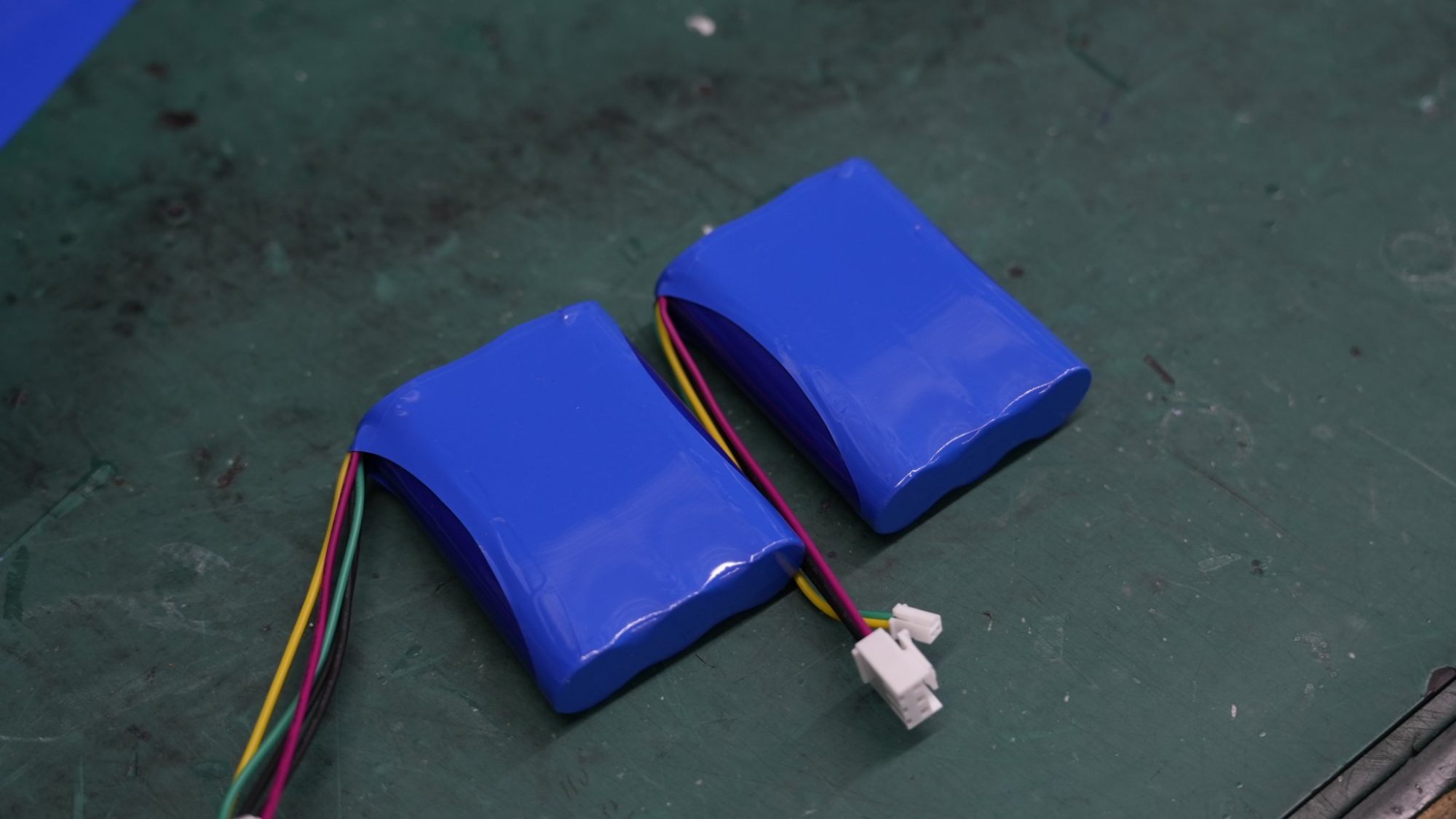
2.1 Verifying Sleep and Ship-Mode Entry and Exit
A mode only counts if you can prove the pack enters it and leaves it on command. Write down the entry condition, the wake sources, and what stays powered for each state. Then test every path.
The following controller-level example is not a battery-pack specification. Its current and latency figures must not be used for pack sizing. Replace them in the released requirements with measurements of the selected controller and complete assembly under documented conditions.
Sleep State | Entry Condition | Exit / Wake Source | RAM Retained | Current | Wake Latency |
|---|---|---|---|---|---|
runtime-idle | Idle thread runs; policy picks the lightest state when the next event is imminent | Any interrupt (timer, GPIO) | Yes | ~3 mA | < 1 µs |
suspend-to-idle | Policy confirms the residency requirement is met | GPIO interrupt (button), RTC expiry | Yes | ~1.5 µA | ~5 µs |
standby | Forced through the power manager; GPIO sense must be configured | GPIO sense; full reboot from main() | No | ~0.3 µA | Full reboot |
The main rule is simple. A deeper state only pays off when the pack will stay asleep long enough to justify entry and exit cost. Use the same thinking for your pack.
Document only the wake sources implemented in the selected architecture, such as an approved charger-detect circuit, button, timer or communications wake input. Specify trigger levels, debounce, timeout and the return-to-sleep sequence. A message cannot wake a transceiver that has no powered wake function.
Define a validated balancing policy for storage and shipment. Balancing consumes energy and can create unequal group drain. Disable or limit it only where consistent with the cell-monitoring and protection strategy, and measure residual tap currents in every series group.
2.2 Whole-Assembly Standby Drain Measurement
Do not trust component datasheets for battery standby current. Measure the complete assembly: BMS, gauge, protection FETs, balancing circuits, and always-on rails. Datasheet numbers assume ideal conditions. Your board adds leakage paths.
Set up a practical measurement. Put the pack in its ship mode, keep it at a controlled temperature, and log current with a meter or a shunt-based logger over a long window. Record the wake events you inject. A robotics dock or an infrastructure backup unit may sit for weeks, so a short bench reading will mislead you.
Define acceptance criteria per program. State the allowed standby draw for each mode, the test duration, and the pass/fail band. Then confirm the sleep and ship-mode functions behave as specified after each wake cycle. A hardware disconnect that fails to latch is worse than no disconnect at all.
Opening the output path does not necessarily remove internal consumption. The BMS supply, cell taps, protection circuits and host interfaces may remain energized. Measure residual drain and possible backfeed with both the host connected and disconnected.
Part 3: Peak Loads, Topology, and Standby Drain Tradeoffs
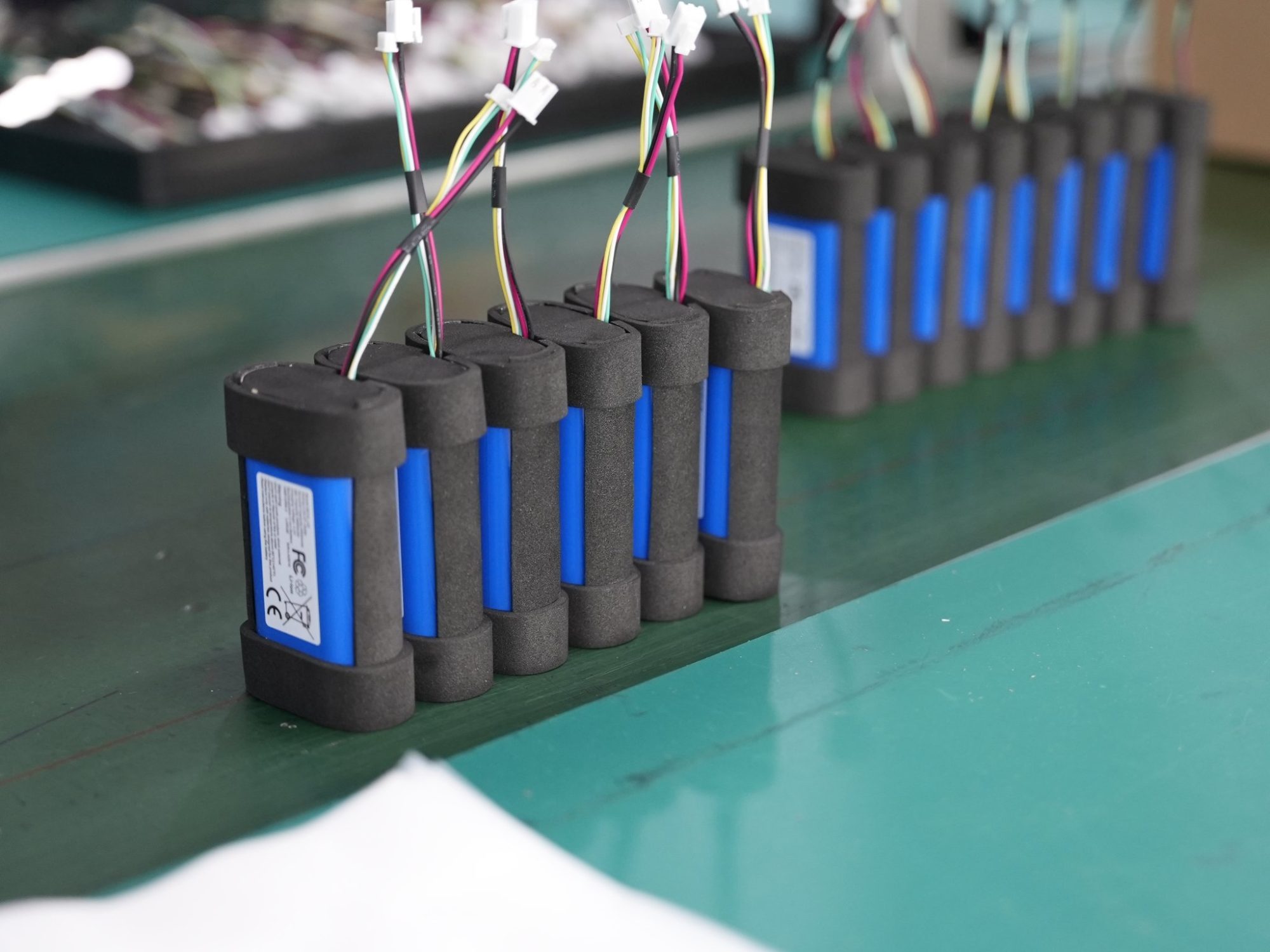
3.1 Load Current Characterization and Pack Topology
Think of standby draw, peak-load capability, and usable backup energy as three separate budgets. The cells, the BMS, and the host power architecture must meet all three at the same time. Start by measuring battery-side current in every mode: shipping, storage, sleep, and ready-to-test. Write down the worst-case pulse amplitude, duration, repetition rate, and inrush. Include the lowest supported pack voltage, because constant-power loads pull more current as voltage falls.
Figure out series and parallel counts from the required voltage range, energy, and current. A 5S2P pack, with five series groups of two parallel cells each, gives about 18.0–18.5 V nominal and 21.0 V maximum with 3.6–3.7 V cells. That is one possible setup, not a universal standard. Check C-rate at the correct level, and account for real current sharing, which depends on resistance and interconnect symmetry. Parallel cells raise capacity and lower equivalent group resistance, but they do not create independent backup packs. Estimate voltage sag across cell groups, wiring, fuses, FETs, and connectors. Then confirm the parallel count meets both energy and thermal needs.
3.2 Buffering Only When the Budget Requires It
Add a capacitor or supercapacitor only when the power budget shows voltage sag or peak current that the cells cannot meet. Buffering needs a designed charging path, voltage compatibility, and inrush control. For an approximately constant capacitor current, capacitance = current × pulse duration / permitted voltage droop. A 5 A, 0.5 s pulse with 1 V permitted droop needs at least 2.5 F ideally, before ESR, tolerance, aging, and temperature margins. The initial ESR drop is additional.
Compare a buffer with a more suitable cell or parallel count using measured pulse demand. Include buffer leakage, charging losses, voltage limits, ESR and inrush control. A buffer can improve transient response but is not a substitute for a validated energy and thermal budget.
Part 4: Battery Draining in Storage and Backup Energy Sizing
4.1 Storage Duration, Margins, and Remaining Usable Capacity
Size backup energy for a clear, defined workflow, not for a datasheet. Write down how long the pack will be stored, the shipment window, and the wake-up events you expect. Then add clear margins for each one. A medical device pack that sits in a warehouse for months needs a different budget than a robotics pack that wakes every day.
The allowances below are hypothetical discussion values, not recommended design limits. Derive efficiency, aging and SOC reserve from the actual duty cycle and avoid counting the same loss twice.
Allowance | Example Value | Purpose in Sizing |
|---|---|---|
Conversion loss | ~15% loss (85% efficiency) | Covers conversion and auxiliary losses |
End-of-life capacity reserve | 15%–25% | Meets duty near warranty end |
Backup state-of-charge reserve | 20%–50% | Protects promised outage energy |
Recharge margin | Site-specific | Confirms recharge before the next event |
Temperature and auxiliary load margin | Site-specific | Covers cooling and cold-weather load |
For a constant electronic drain, capacity loss in Ah = current in A multiplied by storage hours. An illustrative 100 microamp drain over 90 days consumes 0.216 Ah, before cell self-discharge and wake events. Integrate time-varying current separately and check group-level imbalance, not just total pack capacity.
4.2 Partial State of Charge and Low-Voltage Cutoff
Select storage SOC and temperature from the cell and pack manufacturer instructions. Transport SOC limits depend on classification, packing instruction, transport mode and current requirements; they are not a universal 20/80 rule. Budget sufficient remaining capacity for the defined storage interval and authorized startup process.
Set undervoltage protection using the qualified cell limits and load behavior. Output cutoff can leave internal electronics powered, so measure post-cutoff drain and define the permitted storage interval before service. A ship-mode disconnect is not proof of zero leakage or indefinite storage life.
Part 5: Validating Low Standby Power Architecture
5.1 System-Level Drain and Wake-Up Acceptance Tests
Test the design on the whole assembly, not on a bench full of parts. Run each mode through repeated entry and exit cycles. Log current in ship mode and in sleep over a long window at controlled temperature. Inject every wake source and confirm the pack returns to the correct state.
Turn the results into an OEM acceptance checklist. The table below shows the fields your program should sign off before release.
Checklist Item | What You Verify |
|---|---|
Mode definitions | Every state has an entry condition, wake source, and powered-block list |
Measured drain | Whole-assembly current per mode, logged over time |
Margins | Backup energy covers the defined workflow with reserve |
Remaining usable capacity | Capacity at wake-up meets the stated requirement |
A robotics dock or a security panel may sit idle for weeks. A short reading will hide slow leakage, so set the test duration from your real storage window.
5.2 Shipping State-of-Charge and Transport Assumptions
Confirm shipment requirements for the actual UN classification, packing instruction, route and carrier with the responsible dangerous-goods specialist. Use current PHMSA lithium battery guidance and applicable air-transport rules rather than assuming one SOC limit applies to every shipment.
Keep applicable UN 38.3 test evidence and the test summary linked to the shipped design. Transport qualification does not establish acceptable storage duration. Verify that the defined shipping state permits compliant handling and leaves sufficient capacity for the receiving inspection and startup workflow.
These three strategies work together as one system. Mode definitions feed your power budget. That budget sets sleep and ship-mode targets. System-level validation then proves the design works as specified.
Track electronic drain separately from cell self-discharge. Passive balancing and gauge monitoring are real standby drain sources you can control. Size backup energy with clear margins tied to your defined storage and shipment workflow.
Turn this outline into a requirements table and OEM checklist for your custom pack program. Validate the whole assembly rather than trusting component datasheets. Your measured results, not paper specs, decide whether your pack survives long storage with usable capacity intact.
FAQ
What counts as a realistic BMS quiescent current target?
Set a program-specific limit for each mode using the required storage interval and allowable capacity loss. Component datasheets inform the budget, but acceptance requires measured assembly current, periodic wake energy and residual group-level drain.
Why does my pack lose charge when the host is switched off?
The host switch usually sits downstream of the BMS. Protection FETs, the gauge, balancing circuits, and always-on rails keep drawing current. Add cell self-discharge on top. Measure the whole assembly in ship mode to see the real drain.
How do I test drain over a long storage window?
Log current with a meter or shunt-based logger at controlled temperature. Run the test long enough to match your real storage window. A robotics dock or security panel may sit idle for weeks, so a short bench reading hides slow leakage.
Does partial state of charge help during shipment?
A manufacturer-approved partial SOC can reduce storage stress, but the permitted shipping SOC depends on the applicable transport rules. Do not use a general storage recommendation as a substitute for shipment classification and carrier review.
When should I add buffering to the pack?
Add capacitors or supplemental stages only when your power budget shows voltage sag or peak current the cells cannot meet. Buffering adds leakage, cost, and inrush design work. A higher parallel count often solves the same problem with less standby penalty.


