

Quick Answer: Use only packs and connection architectures approved for parallel operation. Check actual terminal voltage, compatible voltage range, impedance, reverse-current limits and BMS state. Matching displayed SOC alone is insufficient; validate controlled connection and fault isolation.
Paralleling complete packs is not the same as paralleling cells. Each pack has its own BMS, so the BMS units must work together. Pack-level protection also changes how failures happen. A matched state-of-charge (SOC) reading alone does not make paralleling safe. Engineers must check the maker’s approval, compatible chemistry and voltage range, the measured terminal voltage difference, and impedance. They also need an approved connection, precharge, and isolation setup. Never connect parallel battery packs directly without control. Never equalize them by hand with cables. This article explains how to prevent cross-current when SOC is unequal. It explains how to equalize SOC safely and how to isolate faults. It also covers defining requirements, design tradeoffs, test acceptance, and an OEM checklist.
Key Takeaways
Confirm manufacturer approval for the exact parallel pack combination.
Check terminal voltage, impedance and reverse-current limits, not SOC alone.
Use controlled connection and validated branch protection.
Test one-pack disconnect, load transfer and communication loss.
Document safe commissioning and service procedures without manual equalization.
Part 1: Managing Unequal SOC in Parallel Battery Packs
1.1 Why Unequal SOC Occurs and What It Risks
Small state-of-charge differences between parallel battery packs are normal. Large or lasting soc differences are not. A steady soc difference of a few percent may just be measurement tolerance. A growing gap, especially one paired with voltage, current, or BMS status mismatches, points to setup errors or bad parts. Engineers should treat that pattern as a fault signal, not a small problem.
Several things cause the drift:
Cell mismatch from manufacturing: no two cells are the same, so small impedance and voltage-SOC differences make parallel cells carry different currents and settle at different soc values.
Uneven aging: resistance and capacity split apart as cells age at different rates, and the gap grows faster once quick fade begins.
Connection and contact resistance: cells farther from the output terminals see higher resistance, and rust or mechanical stress can raise contact resistance more.
Temperature gaps: the lowest-resistance cell pulls the most current, heats up, and loses resistance again, a loop that skews current sharing and speeds uneven aging.
BMS sensing limits: most BMS units measure total module current and only a few temperatures, so single-cell imbalance can stay hidden.
Cross-current is driven by terminal voltage difference and total path impedance, not directly by displayed SOC. Current can exceed either pack charge or discharge limit even when the SOC indicators match. Validate the permitted connection envelope and block connection outside it.
1.2 Equalization Methods and Connection Sequencing
Safe integration starts with checks, not cables. Engineers must confirm the maker approves paralleling, verify compatible chemistry and voltage range, measure the terminal voltage difference, and check pack impedance. They must also use an approved connection, precharge, and isolation setup. Uncontrolled direct connection and hand equalization through cables are never acceptable.
Use the manufacturer-approved preparation and connection sequence for the exact packs. DC-link precharge limits capacitor inrush; it must not be assumed to equalize the energy of complete batteries. Any inter-pack energy transfer requires a specifically designed, rated and controlled circuit. Do not connect packs directly to equalize them.
SOC estimation, cell balancing and inter-pack energy management are different functions. A conventional BMS generally does not actively regulate current sharing between complete packs. If converters or active energy-transfer stages are required, specify them explicitly. Cell balancing inside one pack cannot correct every bank-level mismatch.
Part 2: Cross-Current and Current Distributions
2.1 Causes and Effects of Cross-Current
Having the same SOC does not mean the packs will share current evenly. Two packs at the same SOC can still split current poorly if their impedances are different. Uneven current sharing and lopsided current distributions often point to a bad connection in parallel battery packs. A loose joint adds resistance, and that resistance pushes more load onto the healthier path.
Cause | Mechanism | Effect |
|---|---|---|
Interconnection resistance | Resistance is different between interconnections | Main driver of uneven performance |
Cell-to-cell variation | Lower internal resistance sends more current | Hotter cells age faster, a repeating loop |
Busbar and joint resistance | Cross-section, length and joints all matter | Each cell sends a different current |
Temperature variation | Cold cells have higher internal resistance | Colder cells send less current |
Wiring resistance can add to uneven behavior: a loose or resistive connection makes an extra voltage drop per V = I × R. At 100 A, just 5 milliohms of unwanted resistance gives 100 A × 0.005 Ω = 0.5 V — a big voltage difference in a 12 V lithium battery system.
These effects shape the current imbalance dynamics of any bank. A BMS trip in one pack moves load to the other packs. That extra load can push a second pack past its limit and cause a cascaded trip. Engineers must check fault isolation and allowed reverse current during design, not after deployment.
2.2 Mitigation: Devices, Algorithms, and Wiring
Droop control and master-slave current regulation require controllable conversion stages or another suitable actuator. They are not software features that can automatically regulate directly paralleled passive packs. The table below applies only to architectures with the necessary power electronics.
Algorithm | Architecture | Communication | Sharing method |
|---|---|---|---|
Droop control | Decentralized | None | Reference voltage shifts with load |
Master-slave | Centralized | Required | Master commands slaves |
Design low and suitably matched branch resistance across cables, contacts, switches and busbars. Equal cable length is only one input and does not guarantee equal sharing. Rate every branch for worst-case current, cross-current and fault conditions, and verify current distribution over SOC, temperature and aging.
Part 3: Fault Detection and Isolation
3.1 Fault Types and Isolation Techniques
Parallel packs share current, but they do not share risk evenly. A fault in one pack can pull unwanted current from the healthy packs. Isolation and redundancy are therefore essential design goals, not optional extras.
Assess open circuits, resistive joints, internal and external shorts, sensor faults and stuck switching devices at the complete-pack level. An internal cell fault may not be interrupted by an output fuse. Model backfeed from healthy packs and define containment and isolation measures for each credible fault.
Combine appropriately rated branch protection, local BMS functions and system controls. Verify current direction, voltage, temperature and switching state. A fuse does not guarantee prevention of thermal runaway, and gas or thermal sensors are architecture-specific additions rather than universal substitutes for electrical protection. Review the BMS and PCM architecture.
Select contactors, FET paths, fuses or other disconnects for voltage, prospective fault current, interruption capability and failure modes. Check reverse-current paths, including body diodes and charging paths. Clearing time depends on the exact device and fault; no generic millisecond value proves coordination.
3.2 Coordinating Independent BMS Units
Independent BMS units must coordinate to detect and isolate faults without tripping the whole bank. A BMS trip in one pack transfers load to the remaining parallel-connected packs. That extra load can push a second pack past its limit and cause a cascaded trip. Designers must validate fault isolation and permitted reverse current during development, not after deployment.
Define local protection ownership and system-level coordination. Specify messages, freshness limits, startup authorization and the safe response to lost or contradictory status. CAN error detection does not by itself guarantee deterministic application timing or safe fault handling.
A distributed architecture can reduce some central dependencies but does not automatically eliminate single points of failure. Shared buses, power rails, contactors, sensors and software may remain common-cause vulnerabilities. Analyze the actual architecture and validate degraded operation.
Specify fault detection thresholds and timing from measured normal variation and the risk analysis. Divergent SOC or current can indicate a fault, but sensor error, temperature and aging also affect it. Verify detection coverage, isolation timing and the response of the remaining packs using safe fault simulation.
Part 4: Requirements, Test Acceptance, and OEM Checklist
4.1 Defining Requirements and Design Tradeoffs
Engineers first set the series stack to meet the bus voltage. Then they pick the smallest number of parallel strings that gives the peak current and energy needed. Fewer branches make current sharing and fault analysis simpler. A medical cart pack and a security camera pack both gain from this order. So does a robotics platform with tight space.
Additional parallel branches increase available energy and current only within the approved architecture. They do not automatically create redundancy: the remaining packs must sustain the required load after isolation, and common faults must be addressed. Review the table as qualitative design considerations rather than guaranteed benefits.
Design factor | Tradeoff favoring more series | Tradeoff favoring more parallel |
|---|---|---|
Cable/busbar cost | Lower current allows cheaper conductors | Higher current requires heavier, costlier conductors |
Fault tolerance | String limited by weakest cell | Branches give partial redundancy |
Thermal management | Fewer high-current nodes | More local hot spots, complex thermal mapping |
Some common mistakes need attention. Too many parallel branches cause uneven currents and higher copper cost. Relying only on parallel equalization hides aging differences. Weak cell screening lets one cell limit the string. Tight QA and matching, plus strong BMS logic, cut these risks.
Cell performance is not the same as assembled pack performance. A cell datasheet says nothing about busbar losses or contactor behavior. System validation must test the finished pack.
4.2 Test Acceptance and OEM Checklist
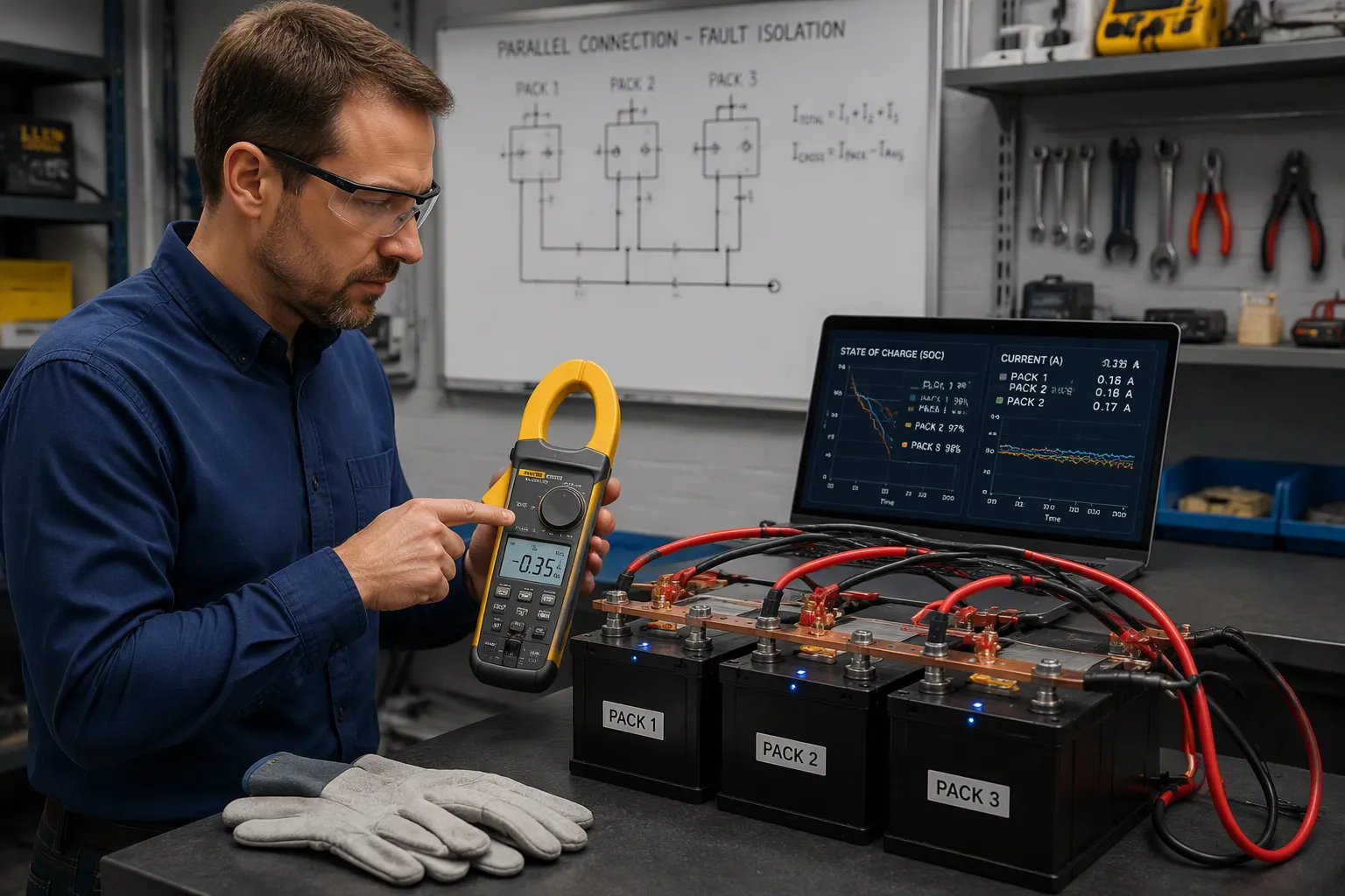
Acceptance testing proves the design works under real conditions. Engineers measure branch currents at commissioning with clamp meters. They check equal path resistance through mirrored busbars and consistent lug lengths. They run parallel current simulation and thermal mapping during design. They confirm the fault detection algorithm tells sensor drift apart from real faults.
The OEM checklist below helps purchasing and quality teams.
Check | Purpose |
|---|---|
Maker approves paralleling | Confirms safe configuration |
Chemistry and voltage range match | Prevents mismatch |
Terminal voltage difference measured | Confirms precharge need |
Equal path resistance verified | Limits uneven current |
Per-cell voltage and temperature monitored | Supports early fault detection |
Contactor and fuse ratings sized | Matches short-circuit current |
System validation completed | Separates pack from cell claims |
Redundancy levels trade size, cost, and complexity. Higher redundancy boosts reliability and raises component count. A careful study per architecture is still needed.
Three requirements work together: an approved compatibility and connection envelope, controlled current paths, and validated fault isolation. Neither equal displayed SOC nor identical wiring alone demonstrates a safe bank.
Paralleling complete packs requires independent BMS units to work together and pack-level protection. You cannot assume what is true for cells applies here. Parallel packs share current, but they do not share risk evenly. Internal faults grow slowly and are hard to spot, because each cell acts like a black box and not all branch currents are measured. That gap makes fault detection and balanced current flow a design job, not something to fix in the field.
Safety and reliability guide every choice. Engineers should go back to defining requirements, test acceptance, and the OEM checklist as the practical takeaway.
FAQ
Can engineers connect two packs at different SOC?
Only within the manufacturer-approved system and connection limits. The critical checks include actual terminal voltage difference, compatible pack design, path impedance, current limits and isolation state. Do not connect packs directly to equalize SOC, and do not treat equal SOC readings as authorization.
How does a bank detect a weak parallel branch?
The BMS compares each pack against its neighbors. Persistent divergence in soc or current sharing signals a developing fault. Good fault detection separates sensor drift from real cell faults, so the system isolates the right component. Early fault detection keeps one weak branch from distorting current distributions across the bank.
Why do parallel packs share current unevenly?
Interconnection resistance, busbar joints, and temperature gaps all shift the split. Uneven current distributions often point to a loose connection. Engineers should mirror wire lengths and check branch currents with clamp meters at commissioning. Fault detection logic should flag any branch that drifts outside its expected share.
What isolation hardware suits parallel packs?
Contactors handle routine isolation and service disconnect because they reset. Fuses and pyro devices interrupt severe short circuits. Engineers size breaking capacity and fuse let-through energy together against the pack’s short-circuit current. Fault detection must command isolation fast enough to protect the healthy packs.
How should independent BMS units coordinate?
Maintain local protection and define system messages, timeout handling and fallback behavior. Master-slave and distributed designs each have failure modes. Demonstrate that lost communications and one-pack isolation do not cause unsafe current or uncontrolled reconnection.


