

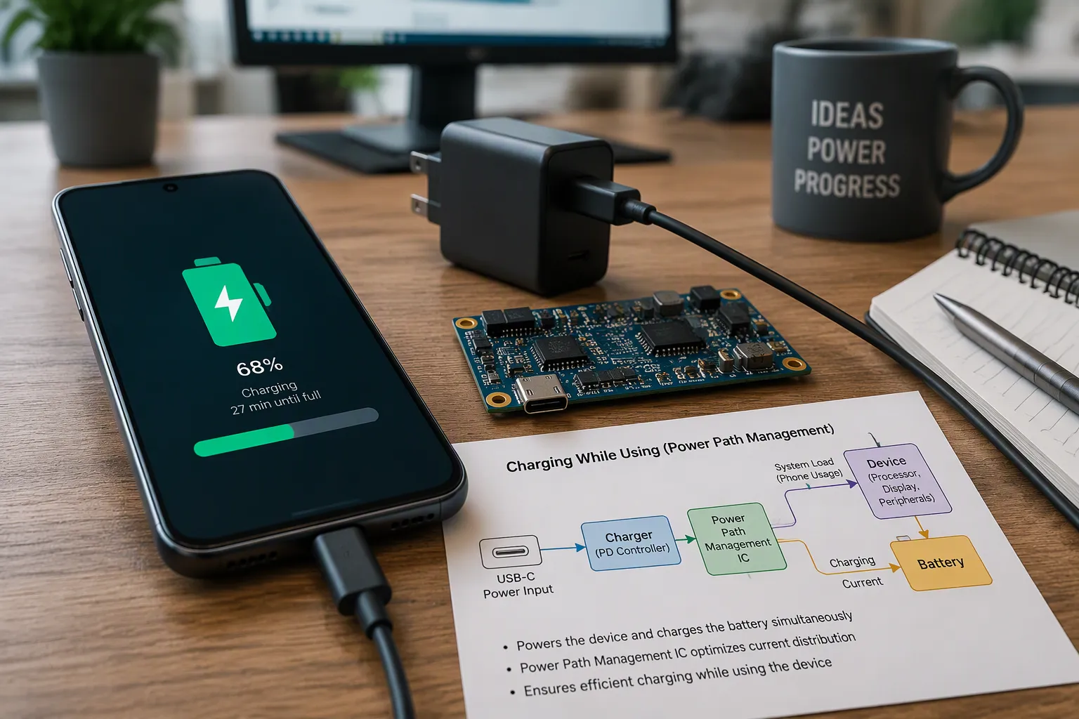
Power-path design, also called load sharing, gives your device a dedicated path from the input source to the system while a separate path charges the battery. Charge terminates on voltage and current thresholds.
Without it, a running device competes with the charger for current. The battery can drain, charge time stretches, and load current corrupts the termination measurement.
This matters to equipment OEMs in medical, robotics, security, infrastructure, and industrial markets sourcing custom lithium battery packs. Tradeoffs stay application-specific and need system validation.
Four parts follow: why power-path matters, key circuit components, operation during charging, and charge termination with verification.
Key Takeaways
Power-path design lets your device run from the adapter while the battery charges separately.
A suitable input budget and power-path controller can reduce unnecessary battery discharge; supplement mode may still draw battery current.
Accurate charge termination happens because the charger measures only the battery current.
Battery-absent or depleted-pack startup depends on the controller, source budget and load profile and must be tested.
Always verify the design on the bench with real measurements before you approve it.
Part 1: Why Power-Path Design Matters for OEM Devices
1.1 The Problem With Simple Charging
A charger that is “compatible” with your pack only regulates current and voltage into the battery. It says nothing about how your device draws power at the same time. That is the gap between general charger compatibility and true load sharing.
Power-path design closes the gap. It gives the system load its own supply path from the adapter and reserves a separate, regulated path for the battery. Your device no longer pulls its operating current through the charger’s battery terminal.
Consider a handheld medical monitor with an NMC pack. The pack specification may allow a defined charge current, yet the device electronics draw a large share of the adapter’s output. A simple charger cannot separate those two currents. A power-path circuit can.
1.2 Battery Drain and Charge-Time Conflicts
Without load sharing, a running device and the charger compete for the same current. When the load exceeds the adapter’s budget, the battery makes up the difference. The pack discharges while plugged in, and the recharge stretches out.
Repeated battery supplementation can affect energy throughput and heat. Assess the actual duty cycle rather than counting every partial event as a full cycle.
Chemistry matters here. LiFePO4, LCO, and LMO packs each respond differently to partial cycling, and cell-level ratings differ from pack-level ratings. Validate the behavior against your actual cell datasheet and system conditions before you commit.
Part 2: Key Components of a Power-Path Circuit
2.1 Ideal Diode and Input FETs
An ideal diode sits at the adapter input. It behaves like a near-lossless switch instead of a real diode. When the adapter is present, it passes current to the system. When the adapter drops out, it blocks reverse flow so the battery does not back-feed the input.
Input FETs handle the same job at higher currents. Their placement shapes the whole design. Low-side FETs sit in the battery ground path and simplify the circuit, yet they lose the ground reference during protection events. High-side FETs sit in the positive path and keep battery and system on a shared ground, which most designers prefer for safety.
Distinguish charger power-path management from common-port or separate-port pack protection. Select the switching arrangement from the circuit requirements and validate reverse-current blocking, inrush and fault behavior.
2.2 Charge Controller and System Load Path
The charge controller regulates current and voltage into the battery. The system load path taps the adapter directly. Together they create an intermediate node, often called the third node, between input, battery, and system. This node enables instant-on operation. Your device boots from the adapter even when the battery is deeply depleted or absent.
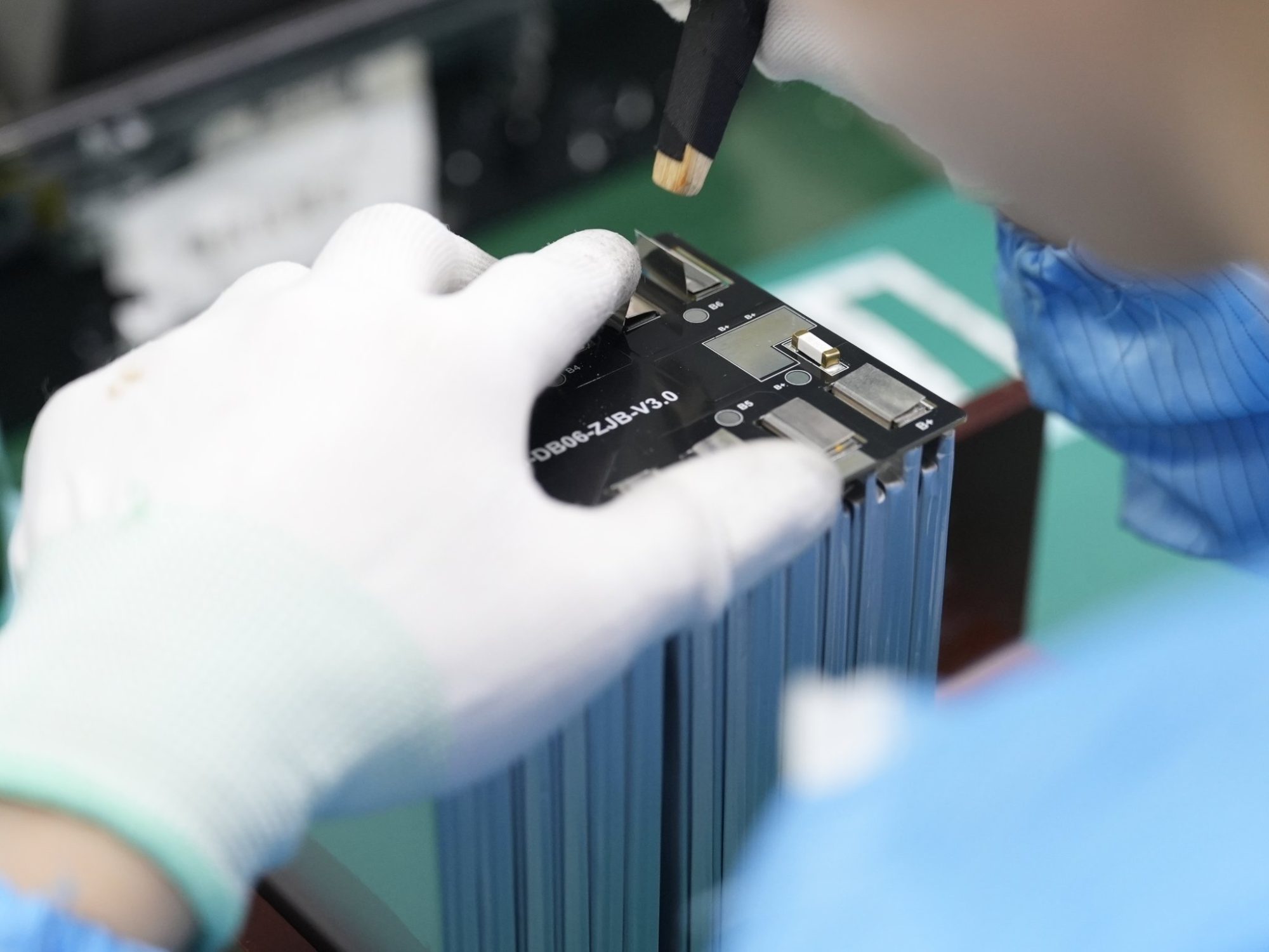
The battery management system supervises the pack behind this node. An analog front-end senses cell signals and flags faults. A fuel gauge estimates state of charge and state of health. A microcontroller runs diagnostics and communications, and a secondary protector adds redundant safety. Cell balancing helps manage series-group imbalance where implemented. You can read more about these functions on the BMS and PCM page. Good Power-Path Design pairs the controller with a BMS that reports accurate cell data.
Part 3: How Power-Path Design Works During Operation
3.1 Powering the System From the Input Source
The adapter carries your system load first. Power-Path Design routes the input current straight to the device electronics, and the battery sits on a separate branch. Your device runs from the wall supply, not from the pack.
The input budget sets the ceiling. Suppose an illustrative adapter delivers a fixed current, and your board draws most of it at peak. Only the remainder can flow into the battery. Size the adapter against the sum of worst-case load and target charge current, then confirm the split on the bench. These numbers are illustrative only. Your real budget depends on the adapter datasheet, the cell datasheet, and system validation.
Check the selected supply and charger derating curves, enclosure temperature and actual cooling conditions. There is no universal ambient derating point, airflow requirement or convection reduction percentage.
Switchover keeps the device alive when the adapter drops. Medical devices such as infusion pumps and ventilators rely on this behavior. Budget for battery safety under IEC 62133 and for cell aging, not just the switching circuit.
Define permitted rail droop and interruption from the actual host requirements. Test adapter removal, reconnection, load steps and protection transitions; the application name alone does not determine interruption tolerance.
3.2 Charging the Battery in Parallel
The charge controller works the battery branch while the system runs. It holds a regulated current into the pack, then tapers as the pack approaches its voltage limit. During normal adapter-powered operation, the system branch is separate from the sensed battery-charge path. Verify supplementation and other modes separately.
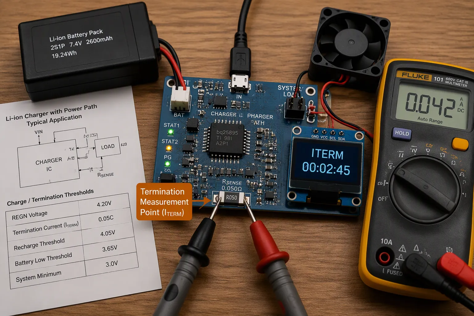
This independence is the point. A simple charger measures one current that mixes load and charge. A power-path charger measures charge current alone. That separation supports accurate termination, which Part 4 covers.
Part 4: How Charge Termination Is Handled
4.1 Voltage and Current Thresholds
A lithium-ion charger runs two phases. In the constant-current phase, it pushes a fixed current into the pack. When the pack reaches its voltage limit, the charger switches to constant voltage and holds that level. The charge current then tapers as the cells fill.
For many CC/CV charger implementations, termination requires battery voltage and charge-current conditions, qualified by controller-specific timers, operating modes and temperature logic. Use the chosen controller and cell documentation, not a universal percentage of rated current.
Voltage limits depend on chemistry and cell specification. Treat these as typical values and confirm them against your cell datasheet.
Derive pack charging limits from the approved cell specification, series count, tolerances and protection settings. Confirm that no individual cell exceeds its permitted conditions.
Specify charge voltage, current, termination criteria, restart conditions and temperature limits together. Lower termination current is not automatically preferable; validate charging time, thermal exposure and cell requirements.
4.2 Timers, Safety Checks, and Verification
Current alone should not end a charge. Add a safety timer that stops the cycle after a defined window, even if ITERM never trips. Add a pack temperature check, and pause charging outside the window your cell datasheet allows. Watch for a pack that never reaches its voltage limit, and flag it as a fault.
Build your requirements list before you approve a design:
Load sharing: confirm the system runs from the adapter while the pack charges.
Charger input budget: size the adapter for worst-case load plus target charge current.
Termination thresholds: set charge voltage and ITERM from the cell datasheet, then verify on the bench.
Thermal limits: check the derating curve at worst-case internal ambient.
Supply switchover: define the behavior when the adapter drops, and test it under load.
Verify each item with bench measurements, not datasheet assumptions. Log charge current, pack voltage, and board temperature across a full cycle.
For a custom pack built around your device, start a custom battery project with our team.
A validated power path separates system load from battery-current measurement and controls source transitions. It does not replace independent battery protection or prove device-level safety. Release the design only after checking the actual load profile, power budget, temperature limits and fault responses.
FAQ
How does load sharing differ from a charger that claims pack compatibility?
Compatibility only tells you the charger regulates current and voltage into the battery. It says nothing about your device drawing power at the same time. Load sharing adds a separate path from the adapter to the system, so your electronics stop pulling current through the charger’s battery terminal.
How do I size the adapter for a device that charges while running?
Add your worst-case system load to your target charge current, then confirm the split on the bench. Check the supply’s derating curve at the hottest internal ambient, not at room temperature. A fanless design must use the convection rating, which is typically lower than the forced-air figure.
Why does system load corrupt charge termination?
A simple charger measures one current that mixes load and charge. If your device draws enough, that combined current may never fall to the ITERM threshold, so the cycle never ends cleanly. Power-path design measures charge current alone, which keeps the termination decision accurate.
Can my device start up with a deeply depleted or missing pack?
Yes, if the circuit provides an intermediate node between input, battery, and system. That third node lets the device boot directly from the adapter. Confirm the behavior on your own hardware, since instant-on depends on your controller and load profile.
What should I verify before approving a power-path design?
Log charge current, pack voltage, and board temperature across a full cycle. Test switchover under load when the adapter drops. Confirm your charge voltage and ITERM settings against the cell datasheet, and check the thermal margin at worst-case ambient. Treat every result as conditional on your duty cycle.
Part 5: Primary Technical Reference
Texas Instruments explains system and battery-current separation in its power-path charger technical article. Component-specific behavior must still be checked against the selected controller datasheet.


