

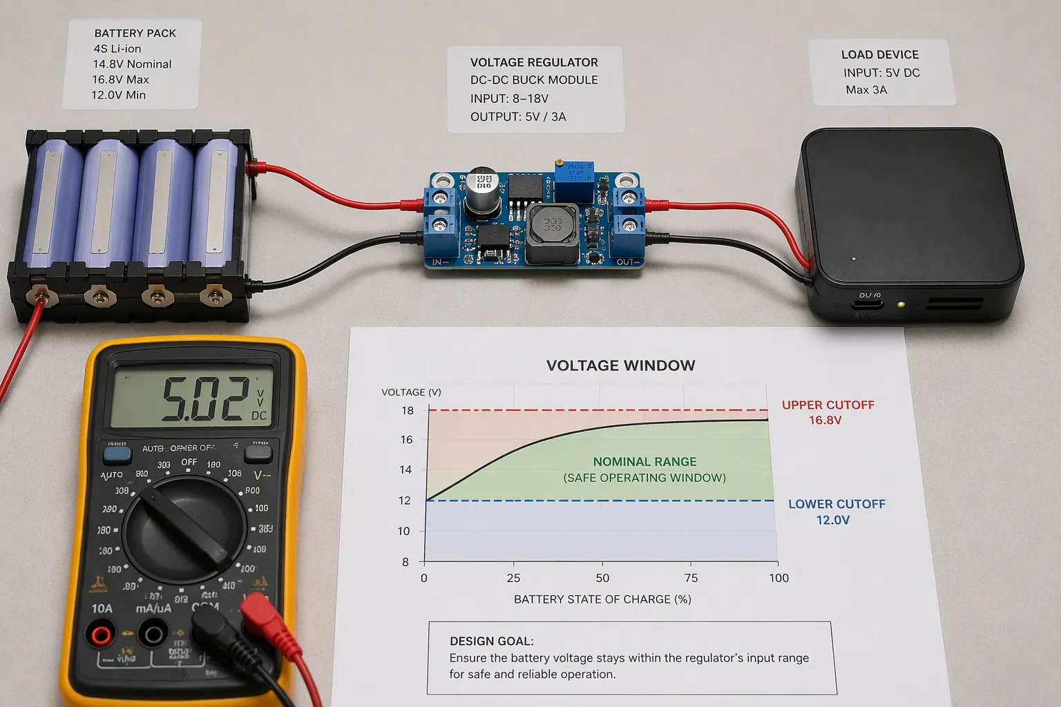
A custom battery pack must be compatible with the complete operating input range of its host, not just its nominal voltage. OEMs should compare maximum charging voltage, loaded end-of-discharge voltage, transient behavior and regulator limits before selecting a series count.
Key Takeaways
Compare the full loaded voltage range, not nominal voltage alone.
Check low-voltage power capability and high-voltage tolerance together.
Measure at the cell groups, pack connector and host input to separate the causes of voltage loss.
Validate startup, charger-connected operation, protection and recovery using controlled revisions.
Part 1: Define the Two Voltage Windows
1.1 Battery voltage is not regulated output
Nominal voltage is a convenient rating. Actual terminal voltage changes with state of charge, current, temperature and aging. Protection thresholds are safety functions, not precise indicators of empty or full capacity.
Obtain charge limits, discharge limits and curves for the selected cell model. Then identify the pack configuration and the effect of interconnects, protection FETs, fuses and connectors. A chemistry label alone does not establish the usable range.
1.2 Identify the host measurement point
Specify normal operating range, startup range, undervoltage lockout, hysteresis and absolute maximum ratings at the actual device connector. A converter’s absolute maximum is not a recommended continuous operating point. Include cable loss and possible charger-connected conditions.
1.3 Create a shared requirements table
Requirement | Reference point | Evidence to request |
|---|---|---|
Maximum normal voltage | Pack output and host connector | Approved charge target, tolerance and transient measurements |
Minimum operating voltage | Host connector and regulated rails | Load-dependent operating boundary and shutdown behavior |
Cell discharge boundary | Individual series groups | Cell-specific conditions and pack protection configuration |
Restart behavior | Host enable and converter input | Rising/falling thresholds, hysteresis and startup load |
Assign an owner to every limit. The battery supplier cannot confirm host compatibility from a nominal voltage label, and the equipment team should not infer the cell operating limits from a converter rating.
Part 2: Check the Low-Voltage Corner
2.1 Account for load-induced sag
Measure startup, pulse and continuous loads at low state of charge, relevant temperature limits and aged conditions. Battery impedance and the complete power path contribute to voltage drop. A simple resistance calculation is a screening estimate, not a substitute for transient testing.
A device may stop while the pack still contains energy because it cannot maintain the required voltage or power. Increasing capacity, changing cell selection, reducing resistance or revising the converter can address different causes; these options are not interchangeable.
As a first-pass circuit model, host input voltage can be approximated as pack terminal voltage minus current multiplied by external path resistance. Include connector pairs, cables and switches that sit between the chosen measurement points. Do not count pack internal resistance twice if it is already reflected in the measured loaded terminal voltage.
Separate a brief voltage excursion from a sustained loss of regulation. Record duration, repetition and the host response. A transient that resets a processor may be unacceptable even when average voltage looks normal; a permitted excursion must still remain consistent with component and cell constraints.
2.2 Preserve cell operating limits
Do not subtract extra sag below the approved cell discharge limit and then treat that voltage as usable design headroom. Determine allowable terminal conditions from the cell specification and validation. Individual series groups may reach their limits while total pack voltage appears acceptable.
Part 3: Match the Converter and Series Count
3.1 Evaluate both ends together
More cells in series may improve low-voltage headroom but raise full-charge voltage. Check both ends before committing to a configuration. A buck converter needs sufficient input headroom; a boost converter and buck-boost converter have different voltage and current constraints.
For an explicitly illustrative example, a 4S pack using cells approved for 4.20 V charging reaches a nominal maximum charging target of 16.8 V before tolerances. This is not the operating specification of every 4S pack.
3.2 Calculate current and thermal demand
A constant-power load draws more input current as voltage falls. Estimate input current from required output power, actual efficiency and input voltage, then verify current limits, heat and wiring losses. Efficiency is operating-point dependent.
3.3 Work through a power-based example
Consider an illustrative instrument requiring 24 W at its regulated output. At an assumed 90% conversion efficiency, input current is approximately 24 W / (0.90 × Vin). It is about 1.85 A at 14.4 V and 2.22 A at 12.0 V. These are calculations, not measured performance or a proposed pack specification.
The higher low-voltage current changes connection losses and converter stress. Repeat the calculation using measured efficiency and the actual dynamic load, then compare it with converter switch-current limits and pack current capability. A converter output-current rating cannot simply be used as its battery-input current rating.
Manufacturer documentation illustrates why input range, UVLO and restart behavior need separate checks. For example, the Texas Instruments TPS63060-EP datasheet describes converter-specific undervoltage lockout and restart behavior. It is a technical reference, not a component recommendation for every pack.
Part 4: Coordinate Shutdown and Protection
4.1 Provide controlled operating margin
Where the application allows, the host should warn, reduce load or shut down before an avoidable undervoltage protection trip. Determine the margin from measurement error, sag, processing delay and the energy needed for the intended shutdown.
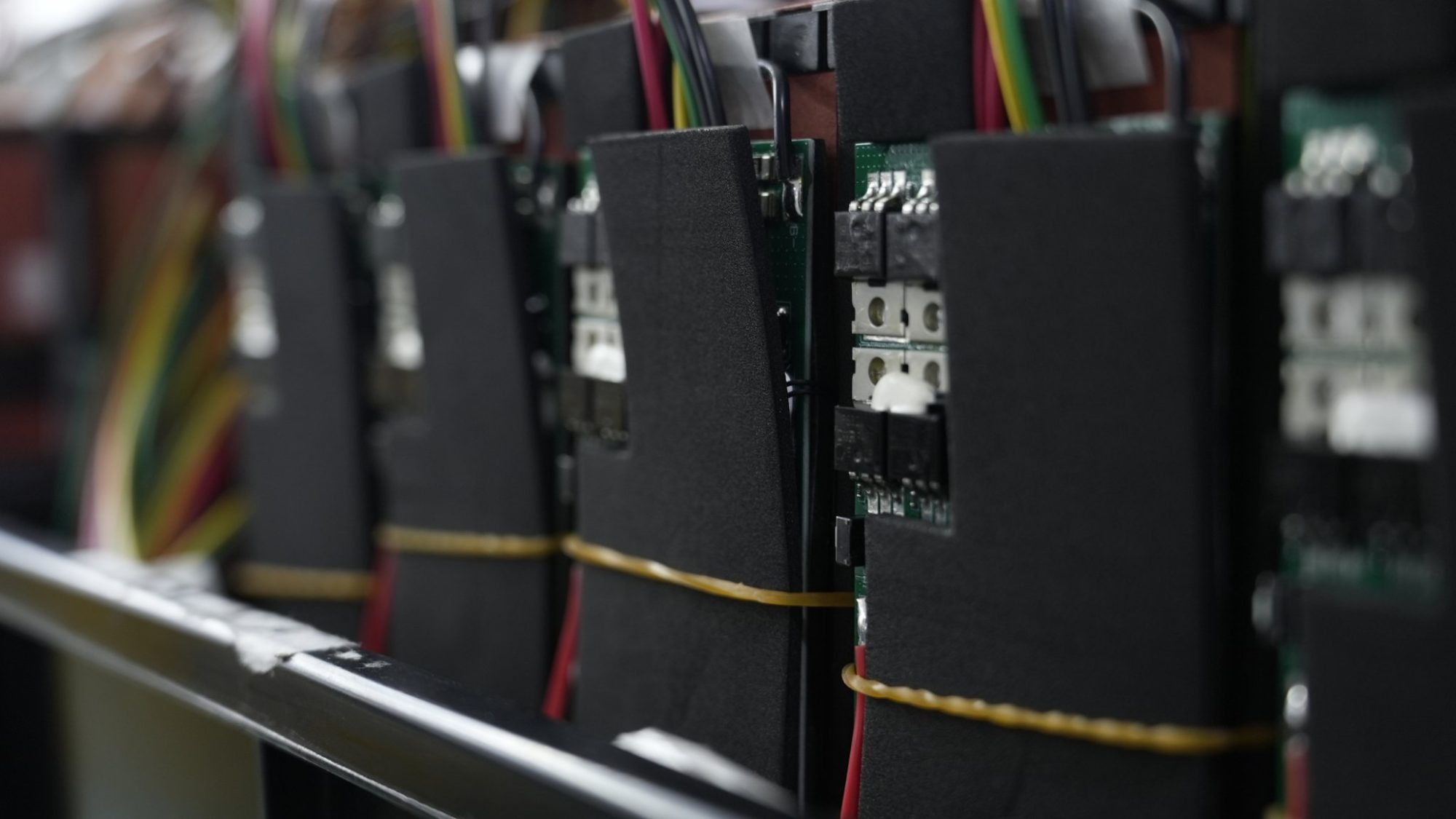
Review BMS and PCM behavior separately. Fast faults may require immediate independent protection; host continuity must not be achieved by disabling essential safety functions.
4.2 Validate recovery
Test load removal, charger connection, startup after protection and operation near the cutoff boundary. Confirm that repeated reconnect cycles do not create an unstable restart loop.
4.3 Consider the application response
A portable analyzer may need time to store a measurement before shutdown. A mobile robot may need a controlled stop while accounting for motor transients. A medical device may require an alarm, alternate power or continued essential performance rather than an immediate stop. Define these responses through the device-level requirements and risk analysis; the industry name alone does not determine a safe response.
Part 5: OEM Validation Checklist
Cell model, approved limits and series/parallel configuration.
Host operating limits and absolute maximum ratings.
Voltage and current at cell groups, pack output and host input.
Startup, pulse loads, temperature corners and relevant aging conditions.
Shutdown, protection, charger-connected operation and recovery records.
5.1 Use a test matrix rather than one runtime run
Operating corner | What to observe | Acceptance basis |
|---|---|---|
Maximum charge and source connection | Host input voltage, overshoot and regulated rails | Normal operating limits and absolute maximum constraints |
Low SOC with startup or peak load | Series-group voltage, pack/host voltage and current waveform | Cell limits, regulation and permitted host response |
Relevant cold/hot and aged conditions | Sag, heat, available energy and shutdown margin | Declared application conditions and lifecycle requirements |
Protection and recovery transitions | Fault flags, switching states and restart attempts | Approved protection and host state sequence |
5.2 Retain a reproducible release record
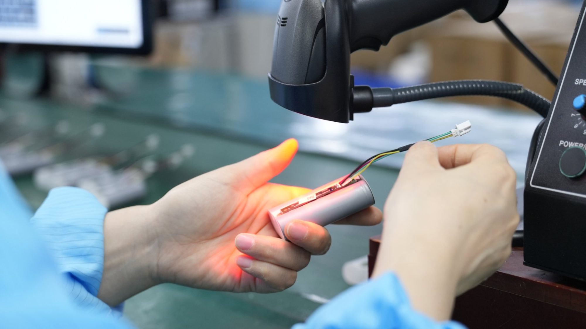
Identify cell and pack models, hardware revisions, firmware, BMS configuration, charger and test equipment. Record temperatures, preconditioning, state-of-charge method, current profiles and measurement locations. Define sample selection from the project risk and variability rather than assuming one pack represents production.
When a cell, connector, cable, converter or firmware changes, assess which voltage, current and recovery checks are affected. Keep acceptance criteria distinct from the observed results so later design changes can be reviewed against the same requirements.
FAQ
Can nominal voltage establish compatibility?
No. Compare the complete loaded voltage range and the host’s permitted operating conditions.
Will a buck-boost converter recover all remaining energy?
No. Cell limits, current capability, converter losses and protection behavior still constrain usable energy.
Where should an OEM start?
Share the host input specification and measured load profile through the custom battery solution inquiry. These inputs support a meaningful pack-level assessment.


