

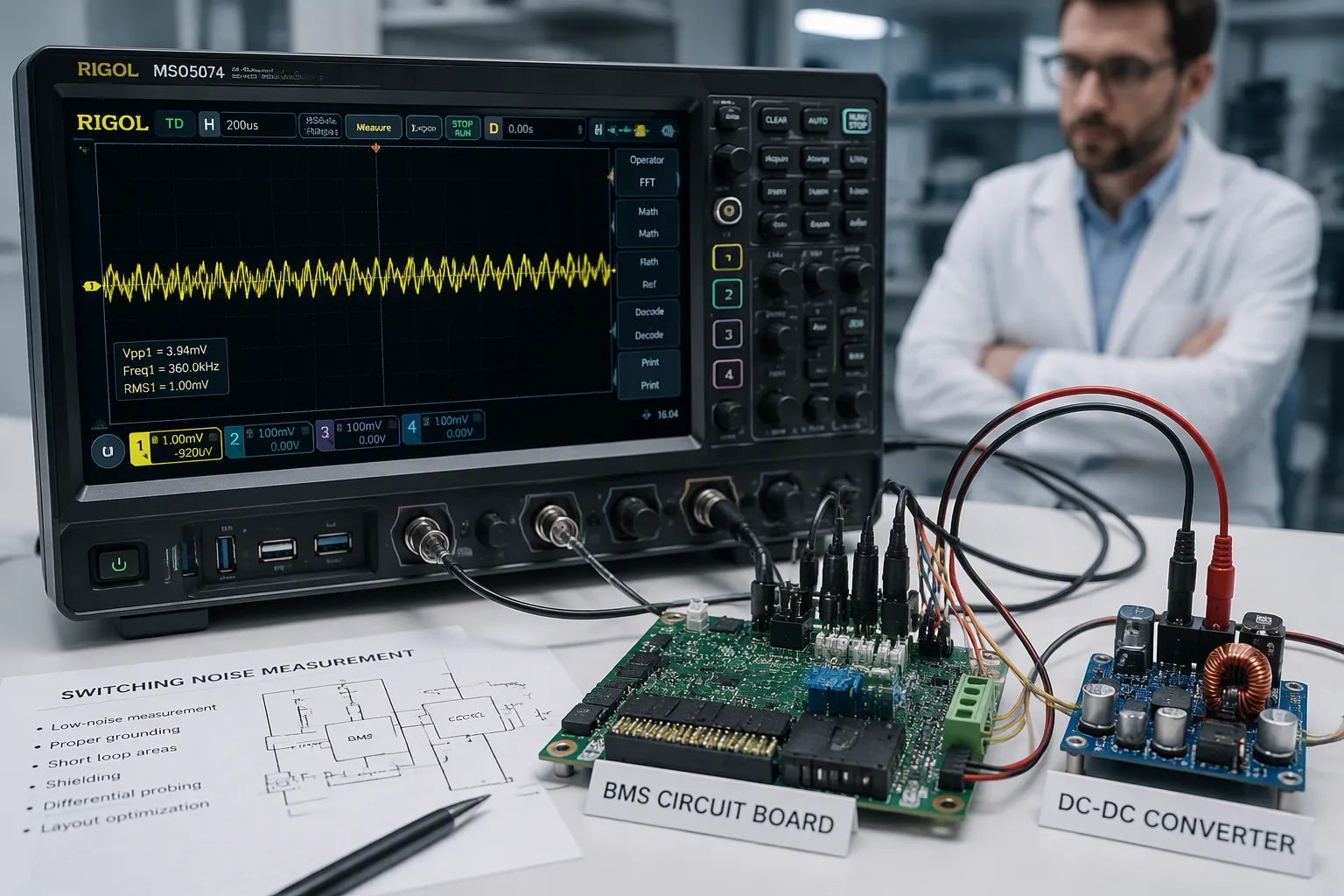
Battery power is not automatically noise-free. A precision instrument may contain a quiet cell source but still experience interference from its protection circuit, fuel gauge, communications and DC-DC converters. OEMs should define the measurement requirement at the instrument level before choosing pack electronics.
Part 1: Define the Measurement Problem
1.1 Specify the affected signal
Record the sensor bandwidth, measurement range, resolution and acceptable error. Distinguish supply ripple from errors observed at the analog front end or final digital result. There is no universal battery-noise limit suitable for every laboratory instrument.
1.2 Identify operating modes
Include idle, acquisition, communications, charging, startup and shutdown. A fuel-gauge update, radio burst or heater cycle may matter only during a sensitive measurement interval. Record timing as well as amplitude.
Part 2: Trace Noise Sources and Coupling Paths
2.1 Separate cell behavior from electronics
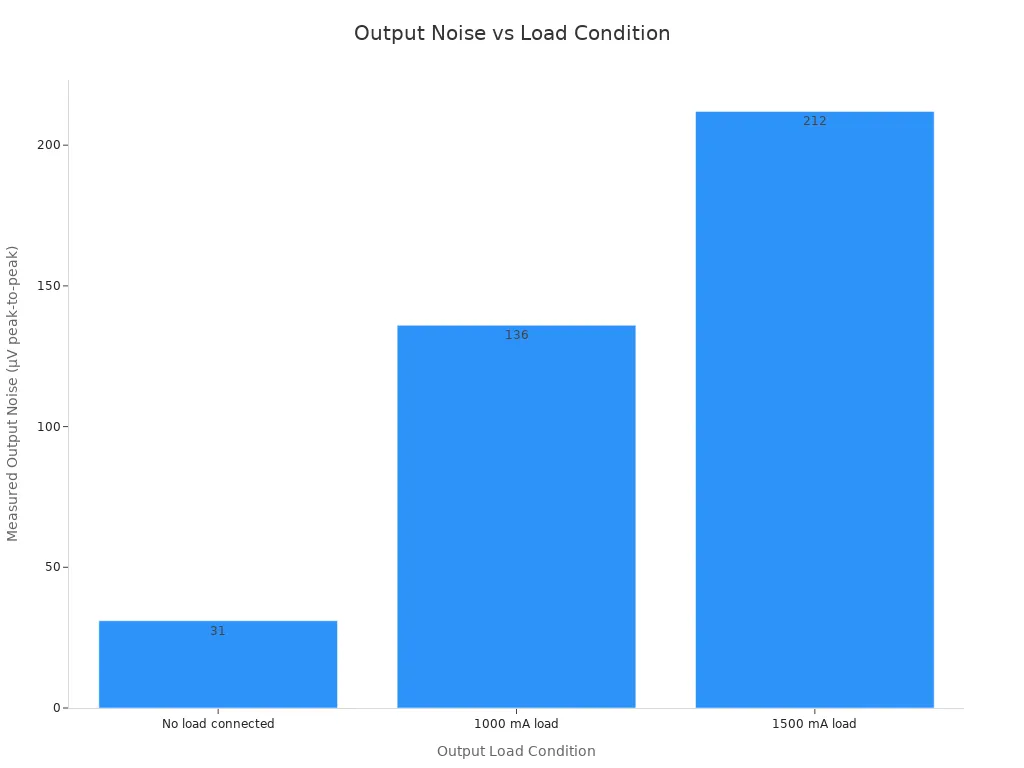
Load-dependent voltage changes, contact resistance and battery impedance can modulate the supply. Switching converters and digital circuits add other disturbances. BMS protection events create larger transitions that should be analyzed separately from small-signal noise.
2.2 Review the complete return path
Inspect common impedance in grounds, power returns, shields and communication references. High-current paths sharing impedance with sensitive references can create measurement error even when the cell voltage is stable. Differential communication does not eliminate all reference and coupling issues.
Part 3: Engineer the Pack and Host Together
3.1 Coordinate electronics selection
Specify the required BMS and PCM functions, communications schedule and operating modes. Do not remove required protection solely to improve a noise measurement. Where practical, compare candidate electronics using the same host and load profile.
3.2 Evaluate filtering and conversion
Select converters using performance over the actual input voltage and load range. Check light-load modes, switching frequency, transient response and interactions with upstream protection.
Filtering is not an automatic cure. An input filter can interact with a converter, and added resistance can increase voltage drop. Validate stability, startup, load steps and temperature. Layout, return paths and decoupling placement often matter as much as component values.
Part 4: Measure Without Creating Artifacts
4.1 Document the test setup
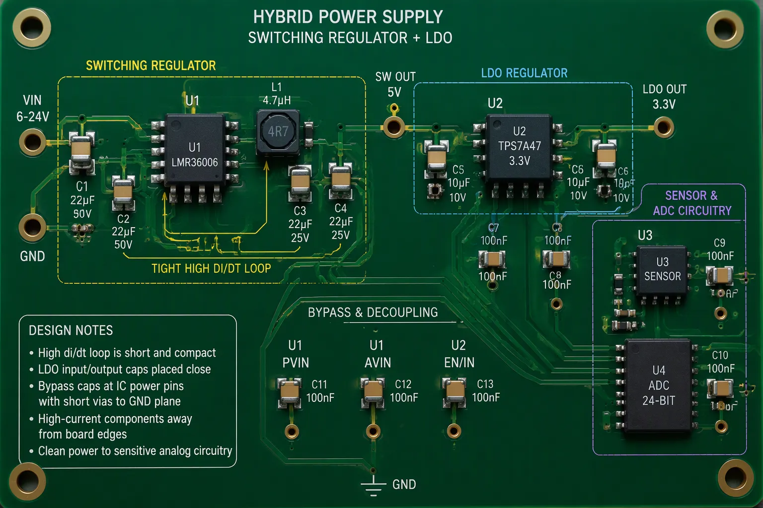
Record probe configuration, grounding, bandwidth, sampling and operating conditions. Long probe ground leads can capture interference that is not representative of the node under test. Use suitable differential or isolated measurements where required for safety and accuracy.
4.2 Correlate noise with device behavior
Measure at the pack output, converter input, sensitive rail and relevant signal output. Correlate observed disturbances with BMS activity, load transitions and communications. Compare a controlled reference supply where useful, recognizing that its impedance and grounding may differ from the battery.
Part 5: Agree on OEM Acceptance Evidence
Defined measurement modes, bandwidth and error limits.
Controlled pack, host hardware and firmware revisions.
Charging and battery-only test conditions.
Waveforms and measurement-system configuration.
Temperature, load and relevant aging corners.
Regression checks after component or firmware changes.
FAQ
Does an LDO guarantee a quiet instrument?
No. Its rejection varies with frequency, operating point and layout, and other coupling paths remain.
Should the BMS communicate less frequently?
Only if timing changes remain compatible with monitoring and safety requirements and demonstrably improve the measurement.
How should a project start?
Provide the sensitive measurement specification and host architecture through the custom battery solution inquiry.


