

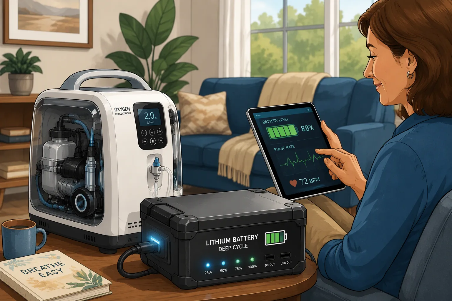
Quick Answer: Size the lithium battery pack for both the compressor’s startup voltage sag and the energy used over its repeated duty cycle. Measure current and device input voltage during startup and repeated pulses, then verify that the pack and device stay within their limits at low charge and under the intended temperature and aging conditions.
Explore medical device battery solutions and see the OEM battery pack testing guide for validation planning.
Key Takeaways
-
Use a clamp meter to measure the compressor startup surge. This surge sets the peak current the battery must supply.
-
Find the average pulse power by multiplying the energy per pulse by the pulses per second. This gives you the average energy demand.
-
Add the startup energy and the pulse energy together to get the total energy for each use cycle. Then set the peak-power budget based on the surge.
-
Pick a battery whose continuous and surge discharge ratings are both higher than the numbers you calculated. Add extra capacity to allow for aging and cold.
-
Test the battery pack using real startup and pulse profiles. This prevents shutdowns and ensures reliable performance.
Part 1: Battery Power for Portable Oxygen Concentrators and Compressor Startup Surge

1.1 Startup Surge in a POC Compressor
The compressor motor makes a brief high-current spike when it turns on. The rotor sits at rest, so the winding draws a current far above its running value until the motor speeds up. This inrush lasts a fraction of a second, but it sets the peak current the pack must deliver. Size the battery or inverter for the spike, not the steady-state wattage. A pack that meets only the continuous rating will sag at every start.
Medical equipment design follows IEC 60601-1, which requires the device to ride through supply transients without hazard. Treat the startup surge as a design input, not an afterthought.
1.2 Measuring or Estimating Surge Current
Measure the surge directly whenever you can. A clamp meter with inrush capture records the peak current during the first cycles after switch-on. Repeat the test several times and keep the highest reading. Check the result against the manufacturer label and the datasheet surge rating. The U.S. Department of Energy publishes motor load data that helps with estimation when measurement is impractical. Estimate from the locked-rotor-to-running current ratio, which commonly falls in a multiple of the continuous draw for small compressors.
Take a medical cart compressor as an example. Its label shows 300 W continuous. An inrush capture reads a peak several times higher for a few milliseconds. That peak, not the 300 W, defines the battery power for portable oxygen concentrators in this design. Record the peak, its duration, and the supply voltage at which it occurs. These three values feed the sizing work in Part3.
Part 2: Repeated Pulse Power and Average Energy Demand
2.1 Energy per Pulse and Duty Cycle
Pulse-dose delivery sends a small amount of oxygen at the start of each breath. Each dose uses a set amount of compressor and valve energy. Multiply that energy per pulse by how often pulses happen, and you get the average draw. Duty cycle is the part of each breath cycle when the compressor is actually working. A short pulse with a long rest between breaths keeps the duty cycle low.
Pulse-dose settings change the average power draw, so runtime from a given capacity changes with them. LoveGo Medical notes that pulse dose tends to be more efficient and can extend battery life, and that higher LPM settings drain the battery faster. The same source reports 1 to 8 hours of operation on a full charge, depending on the output setting. Oxygen Concentrator Store publishes runtime curves across flow settings for several devices, and the chart below shows how steeply duration falls as the setting rises.
2.2 Calculating Average Power
Average power = energy per pulse × pulses per second. Keep energy in joules and frequency in hertz, and the result comes out in watts. This number is an average, not a peak. The startup surge from Part1 still sets the peak current your pack must survive.
Here is a small example with sample values. A pulse costs 2 J, and the device fires 10 pulses per second. Average pulse power = 2 × 10 = 20 W. Drop to 5 pulses per second, and the same device averages 10 W. Halve the pulse rate and you halve the average demand. Use this average as the energy term in Part3, where you combine it with the startup event.
Part 3: Combining Startup and Pulse Loads
3.1 Energy per Use Cycle and Peak Power
One use cycle is one full session away from the wall outlet. Its energy is the startup energy plus the pulse energy added up over the session. Startup energy = surge power × surge duration. Pulse energy = average pulse power × session time. Add the two terms and you have the watt-hours the pack must deliver per cycle.
The peak-power budget comes from the surge, not the average. Peak power = highest surge current × pack voltage at that moment. Size the pack’s continuous and surge discharge ratings above this value. A pack that meets the average but not the peak will fail at every compressor start.
3.2 Startup Sag and Nuisance Shutdown
Startup sag is the voltage drop you see when surge current flows. Internal resistance in the cells causes part of it, as Epectec explains in its guide to designing battery packs for peak power and pulse loads. The rest comes from the current path. Zerne Battery lists the sources of pack-level voltage drop: cell electrochemical response, cell-to-cell imbalance, interconnect resistance, weld or terminal resistance, the BMS conduction path, fuse resistance, cable resistance, connector contact resistance, protection-system response, and measurement-lead effects. A cell can pass a standalone test while the finished pack sags badly.
This matters for battery power for portable oxygen concentrators because the device undervoltage lockout or the BMS protection circuit reacts to the droop. The pack still holds charge, yet the concentrator shuts down mid-use. Epectec warns that a pack which survives one short pulse may not support repeated pulses without voltage sag, heat buildup, accelerated aging, or protection circuit shutdown. Check the whole current path, not just the cells. A high-capacity cell can carry a lower maximum discharge rating than a smaller power cell, so match the cell to the pulse profile.
The BMS is your safeguard here. A properly specified protection board with adequate current-sense and FET ratings rides through the surge without tripping. Review the BMS and PCM design guidance at https://www.large-battery.com/bms-and-pcm/ before you lock the pack specification.
For runtime, use the runtime-division method. Divide your hours away by the documented runtime at the prescribed pulse setting. A session of 4 hours against a documented 8-hour runtime needs half the rated capacity. Add margin for aging and degradation, because capacity fades over the pack’s life and the end-of-life pack must still finish the session.
Part 4: Battery Selection, Margins, and Sizing Example

4.1 Capacity, Discharge Rate, and Chemistry Fit
Capacity sets how long the pack runs. Discharge rate sets whether the pack can handle the surge. You need both numbers, plus a voltage platform that matches the device input.
Check two discharge ratings on every pack you consider: continuous and surge. The continuous rating must be higher than your average pulse draw. The surge rating must be higher than the compressor inrush peak from Part1. A pack rated only for continuous current will sag at every start.
Chemistry decides the trade-off between weight, life, and power. The table below gives cell-level reference ranges only. Treat them as starting points for cell selection, never as pack guarantees.
|
Chemistry |
Platform voltage |
Specific energy (cell) |
Cycle life (cell) |
|---|---|---|---|
|
LCO |
3.7 V |
180–230 Wh/kg |
500–1,000 |
|
NMC |
3.6–3.7 V |
160–270 Wh/kg |
500–1,000 |
|
LiFePO4 |
3.2 V |
100–180 Wh/kg |
2,000–5,000 |
|
LMO |
3.7 V |
120–170 Wh/kg |
300–700 |
Flash Battery reports LMO at 150 Wh/kg and 350 Wh/l with a 1C to 10C discharge range, and notes LMO use in medical equipment and power tools. The same source lists LFP at 177 Wh/kg and 384 Wh/l with more than 4,000 cycles and a 1C/3C range. Wevolver puts LFP nominal voltage near 3.2 V against about 3.6 V for many lithium-ion cells. The IEA reports that LFP packs run about one-fifth lower by mass and about one-third lower by volume than NMC packs.
Where each fits: LMO suits high-power pulse duty in a light pack. LiFePO4 suits long-life, high-cycle medical fleets. NMC balances energy and power for mid-weight portables. LCO suits space-limited, energy-first designs. Solid-state and lithium-metal reach 300–500 Wh/kg where supported.
Add margins for aging, temperature, and surge headroom. Capacity fades over life, cold reduces available energy, and the surge peak needs current headroom above the measured value. Confirm whether the device runs from AC, DC, or battery, because each source has its own sag behavior.
4.2 Worked Sizing Example
For a worked example, measure average power at the battery terminals over a representative operating cycle. A hypothetical 40 W average over two hours requires 80 Wh of usable energy at that load. If startup is included in the measured average, its energy is already accounted for. Validate the peak separately with a time-aligned current and device-input voltage trace, including at low charge and under representative cold and aged conditions.
FAQ
How do I know whether my pack is undersized or oversized?
Compare the pack’s surge rating against your measured inrush peak. A pack that is too small sags at every compressor start and trips the BMS or device lockout. A pack that is too big adds weight and cost without improving runtime. Match both discharge ratings to the real profile.
Why does the concentrator shut down when the battery still shows charge?
Startup sag pulls the pack voltage below the undervoltage lockout threshold. The cells still hold energy, but the droop during the surge trips protection. Check the full current path: interconnects, welds, fuses, cables, connectors, and the BMS conduction path.
Can I size the pack from the continuous wattage alone?
How do pulse-dose settings change my runtime estimate?
Higher pulse rates raise average power, so the same capacity delivers fewer hours. Use the runtime-division method: divide your hours away by the documented runtime at the prescribed setting. Add margin for aging and cold temperature.
Which chemistry fits a pulse-heavy medical pack?
LMO suits high-power pulse duty in a light pack. LiFePO4 suits long-life, high-cycle fleets. NMC balances energy and power for mid-weight portables, and LCO suits space-limited, energy-first designs. Treat cell-level ranges as starting points, never as pack guarantees.


