

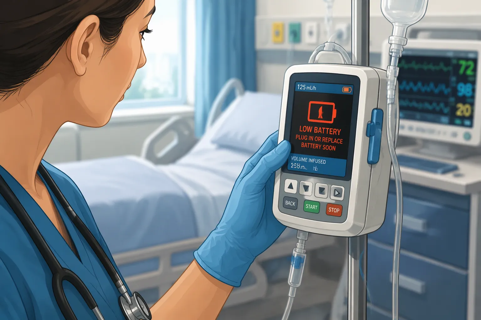
Quick Answer: Define the low-charge warning margin as the minimum usable time between the alarm and the required device action. Verify it under representative high loads and at the intended temperature and battery aging limits, using the device’s defined safe response as the acceptance criterion.
Explore medical device battery solutions and see the OEM battery pack testing guide for validation planning.
This post gives you a practical method to calculate that margin. You will also get a validation path that holds up under aging, cold, and peak load. IEC 60601-1-8 sets the alarm requirements, and ISO 14971 frames the risk file. Both anchor the guidance you will apply to your own Battery Low-Charge Alarms.
Key Takeaways
-
Set the warning margin using the worst-case load, cold temperature, and aging.
-
Test the alarm-to-stop time on packs that are old, cold, and under peak load.
-
Pick a battery type that shows a clear drop in voltage so the alarms work reliably.
-
Link every alarm decision to the IEC 60601-1-8 standard and the ISO 14971 risk files.
-
Check the margin again whenever the battery, chemistry, or firmware changes.
Part 1: Battery Low-Charge Alarms and the Warning Margin
1.1 Defining the Margin in Runtime, Capacity, and Voltage
You can show the warning margin in three units. Runtime margin is the minutes left after the alarm sounds. Capacity margin is the charge still in the pack at that moment. Voltage margin is the gap between the alarm threshold and the cutoff voltage. Each unit answers a different question, and a strong design tracks all three.
1.2 Alarm Fatigue and Nuisance-Alarm Trade-Offs
An alarm without a validated margin fails twice. It fails safety when it fires too late. It fails usability when it fires too often, because clinicians learn to silence it. Both outcomes wear down trust in your Battery Low-Charge Alarms.
Filtering, suppression, and reduced detection sensitivity are the standard levers. Filtering smooths short voltage droops under peak load. Suppression blocks the alarm during known high-current events. Reduced sensitivity widens the trigger band. Each lever cuts nuisance alarms, and each one also delays a true alarm. Write that delay down in your risk file.
Make the threshold configurable. Let users set the alert percentage instead of locking a fixed value. A configurable threshold lets a hospital match the margin to its workflow, and it keeps the alarm useful across care settings.
Part 2: Factors That Drive Margin Setting
2.1 Chemistry Trade-Offs: LCO, NMC, LiFePO4, LMO
The chemistry of your cell sets the shape of the discharge curve. That shape decides how much warning time a voltage threshold can give you. The ranges below are cell-level references only. They are not pack guarantees, because pack design, thermal management, and depth of discharge all shift the real numbers.
|
Chemistry |
Nominal voltage |
Specific energy (cell) |
Cycle life (cell) |
|---|---|---|---|
|
LCO |
3.6 V |
150–200 Wh/kg |
500–1,000 |
|
NMC |
3.6–3.7 V |
150–220 Wh/kg |
1,000–2,000 |
|
LiFePO4 |
3.2 V |
90–160 Wh/kg |
3,000–5,000+ |
|
LMO |
3.7 V |
120–170 Wh/kg |
300–700 |
Each chemistry fits a different job. LCO suits compact consumer electronics and small handheld monitors where energy per gram matters most. NMC serves medical carts and robotics platforms that need a balance of density and cycle life. LiFePO4 fits infrastructure, transportation, and security systems that cycle hard and value a flat discharge curve. LMO works well in power tools and industrial devices that draw high current in short bursts.
The flat LiFePO4 discharge curve makes terminal voltage alone a weak indicator of remaining charge. Validate the estimated reserve against measured runtime and account for load, temperature and aging.
2.2 Power Profile, Temperature, and Aging
Peak load pulls the terminal voltage down before the pack is truly empty. A defibrillator charging capacitor or a surgical robot moving an arm can sag the voltage past your threshold and fire a false alarm. Size the margin against the worst-case load, not the average draw.
Temperature changes the picture again. Battery University reports that a cell stored at 40°C and full charge retains 65% of its capacity after one year, while the same cell at 25°C and 40% charge keeps 96%. Cold cuts available capacity and runtime, so a margin validated at room temperature may fail in a cold ambulance or an unheated storage room.
Aging erodes the margin quietly. Today’s Medical Developments notes that a battery on its 100th cycle may hold only 90% to 95% of its new charge, and the industry treats 80% of original capacity as end of life. Coulomb counting tracks current flow but misses aging and self-discharge. Build your margin on the aged, cold, peak-load case, and the fresh pack will always have headroom.
Part 3: Calculating the Warning Margin

3.1 From Worst-Case Load to Required Runtime
Begin with the load profile, not the battery datasheet. Keeppower’s medical pack selection guide says a portable device must run for eight hours and keep a 30-minute low-battery reserve. The engineering team measures power across display brightness, wireless transmission, alarms, and worst-case processing. Then it applies conversion loss and end-of-life capacity assumptions before setting minimum pack energy.
Punch Through describes a repeatable way to build that profile. Capture the common operations from each system interaction, such as a button press that starts therapy, wireless communication, or sensor sampling. Estimate how often each operation happens in the default case and the worst case. Run each operation on real hardware, then record the current draw with a power profiler. Record idle and sleep current too. Turn those measurements into energy per operation, then into total energy over a shift or a day. Divide pack capacity by that consumption to get runtime for each case.
Automated test scripts make this practical. Hardware-in-the-loop rigs can run idle states, radio advertising at different intervals, sensor sampling, and product-specific functions while a profiler logs average sleep current, peak current, and charge per operation. Compare each result against your power budget.
Then derate. Critical Power Battery Solutions shows the pattern with a 12 V, 300 Ah pack: 3,600 Wh of total energy, 2,880 Wh usable at 80% depth of discharge, and roughly 4 hours against a 720 W load. Discharge rate, temperature, and aging pull that planning figure down further. The same source applies a combined derating factor of 0.6 to 0.7 for a 10 °C environment on a high-rate discharge, and adds a 20 to 30 percent design margin on top.
3.2 Converting Runtime into an Alarm Threshold
Now turn runtime into a threshold. Suppose your worst-case clinical task needs 20 minutes, and your validated alarm-to-stop time is 30 minutes. The threshold must leave at least 30 minutes of usable energy at the aged, cold, peak-load condition. Express that reserve as a percentage of usable capacity, then map it to the voltage or state-of-charge point where your Battery Low-Charge Alarms should fire.
A 1.25 safety factor on calculated runtime is a common starting point, per Ahace Tech. Aging wears down the reserve over the service life. Ahace Tech models remaining capacity as initial capacity times (1 minus the annual degradation rate) raised to the number of years, so a pack losing 10% a year keeps about 73% after three years. Set the threshold against that aged figure.
When the pack reaches a low threshold such as 10%, the device should give a clear visual and audible low-battery indication. A configurable alert percentage lets clinical users match the reserve to their workflow. A battery management system with cell-level monitoring and state-of-charge estimation makes this conversion far more reliable than voltage alone; our BMS and PCM overview at https://www.large-battery.com/bms-and-pcm/ covers the architecture options.
Part 4: Validating Battery Low-Charge Alarms

4.1 Bench, Environmental, and Aging Test Protocol
Validation begins on the bench with a new pack. Then you repeat the test on an aged pack, a cold pack, and a pack under peak load. Each time, you measure one number: the time from alarm to device stop. Run the new pack at room temperature first to set a baseline. Then cycle the pack to its rated end-of-life capacity and repeat. Then soak the pack at your lowest specified operating temperature and repeat. Then apply the worst-case load profile from Part 3 and repeat. Every run must still deliver the full clinical task time after the alarm fires. A margin that passes only the new, warm, light-load case is not validated.
Astute Labs frames the alarm checks you must run against IEC 60601-1-8. The alarm must be correctly prioritized, audible in the intended environment, visually recognizable, timely, traceable to the risk management file, and functional during relevant fault conditions. Intertek summarizes the same standard across six areas:
|
Area |
What It Means in Practice |
|---|---|
|
Alarm Prioritization |
Telling high, medium, and low priority conditions apart |
|
Signal Characteristics |
Standard tones, patterns, and visual indicators |
|
Detectability |
Making sure alarms can be seen and heard in intended environments |
|
Distinguishability |
Making alarms clearly different from one another |
|
Alarm Information |
Giving clear meaning and context for user action |
|
Risk Management Integration |
Matching alarm behavior with ISO 14971 processes |
Same Sky Devices notes that the standard separates physiological alarms from technical alarms, and that a low-charge warning is a technical alarm. Confirm your Battery Low-Charge Alarms are distinguishable from therapy and monitoring alarms. Record the delay from the simulated trigger point to the auditory and visual signal, and log any software processing delay against your defined limit.
4.2 Clinical Evaluation and Alarm-to-Stop Time
Bench data does not prove clinical safety. Take the validated alarm-to-stop time into the intended use environment and confirm the warning is perceptible against real background noise. Astute Labs warns that the most common battery-related safety failure is not a battery event. It is a delayed or unclear warning. Reviewers want clarity on what the device does as voltage falls, what safety state it enters, and how early the user is told.
Build an alarm risk assessment around those questions. Patient Safety Solutions recommends asking what items use batteries, what patient risk follows a battery failure, how the device warns when charge is low, whether that warning is audible and visible, and who checks battery status and how often. Add a failure mode and effects analysis for any secondary alerting path, such as pagers that carry alarms to staff. Patient Safety Solutions also urges an organizational battery management program tied to the alarm safety program.
Part 5: Regulatory Alignment and Risk Management
5.1 Aligning with IEC 60601-1-8 and ISO 14971
IEC 60601-1-8 sets the rules for how alarms must act, and ISO 14971 sets the rules for the risk work behind them. Treat them as one system. Your alarm threshold, priority, and signal design must trace back to a hazard in the risk file. The risk file must also record the leftover risk you accept.
Blue Goat Cyber describes a traceability matrix that links five items in order. Each row carries one complete chain from threat to proof:
-
The threat or hazard found during analysis.
-
The risk it creates.
-
The requirement written to address it.
-
The control built to meet the requirement.
-
The verification evidence proving the control works.
Every hazard in your analysis needs a row with a linked requirement, control, and verification result. The other choice is an explicit, justified acceptance of leftover risk in the risk management file. Apply the same discipline to your Battery Low-Charge Alarms, and reviewers can follow any alarm decision from hazard to test record.
5.2 Documentation and Design-Review Traceability
Altium Resources lists what reviewers check in a medical device design review. They confirm that acceptance criteria allow conformance evaluation under 21 CFR 820.30(d). They also confirm that requirements trace to user needs and hazards. For electronics, they verify several items:
-
Environmental limits and power budget with derating.
-
Creepage and clearance.
-
Alarm logic and essential-performance thresholds, each traced to risks and standards.
-
Human-factors outputs, reviewed against IEC 62366-1.
Home-use devices also bring IEC 60601-1-11 into scope. The review outputs lock your baselines: an approved Design Input Specification, an updated traceability matrix, and a refined verification and validation strategy.
Seezo describes how findings map to the design element that triggered them, the control requirement under review, and the decision being made. That mapping supports Design History File traceability from architecture to threat, mitigation, and acceptance. It can also reference FDA cybersecurity guidance, IEC 62304, and ISO 13485 design control clauses. Log every open item with an owner and a due date.
Your warning margin comes from three inputs: worst-case runtime, chemistry behavior, and load profile. You then prove that margin by testing it under aging, cold, and peak-load conditions. A margin you assume is just a guess. A margin you test is real evidence.
Before you sign off, go through a short checklist. Check the alarm threshold against your aged, cold, peak-load case. Make sure the validated alarm-to-stop time covers the whole clinical task. Make sure every Battery Low-Charge Alarms decision traces back to IEC 60601-1-8 and your ISO 14971 risk file.
Look at the margin again whenever the pack, cell chemistry, or device firmware changes. A new cell or a firmware update can change runtime and alarm delay. Re-run validation at that point, and your margin stays up to date.
FAQ
How do you pick the low-charge alarm threshold for a medical device pack?
Start with the longest clinical task time in the worst case, then add your proven alarm-to-stop time. Show that reserve as a percentage of usable capacity at the aged, cold, peak-load condition. Map it to the voltage or state-of-charge point where the alarm should fire. A fixed 10% alert is a starting point, not a proven answer.
Why does a low-charge alarm fire too early on some packs?
Peak load pulls the terminal voltage down before the pack is really empty. A defibrillator charging its capacitor or a surgical robot moving an arm can drag voltage past the threshold. Set the margin against that worst-case draw, and filter short droops so the alarm shows real remaining energy.
Does cell chemistry change the warning margin?
Yes. The flat discharge curve of LiFePO4 makes voltage alone a weak indicator of remaining charge. NMC and LCO curves slope more, so the same threshold maps to different remaining capacity as the pack ages. Treat cell-level ranges as references only, never as pack guarantees.
How do you validate the time from alarm to device stop?
Test a new pack at room temperature first to set a baseline. Then repeat on an aged pack at end-of-life capacity, a cold pack at your lowest specified operating temperature, and a pack under the worst-case load profile. Every run must still deliver the full clinical task time after the alarm fires.
Which standards govern the alarm and its risk file?
IEC 60601-1-8 sets alarm priority, signal characteristics, detectability, and distinguishability. ISO 14971 frames the risk work behind them. Home-use devices also bring IEC 60601-1-11 into scope, and human-factors outputs are reviewed against IEC 62366-1. Trace every alarm decision from hazard to test record.


