

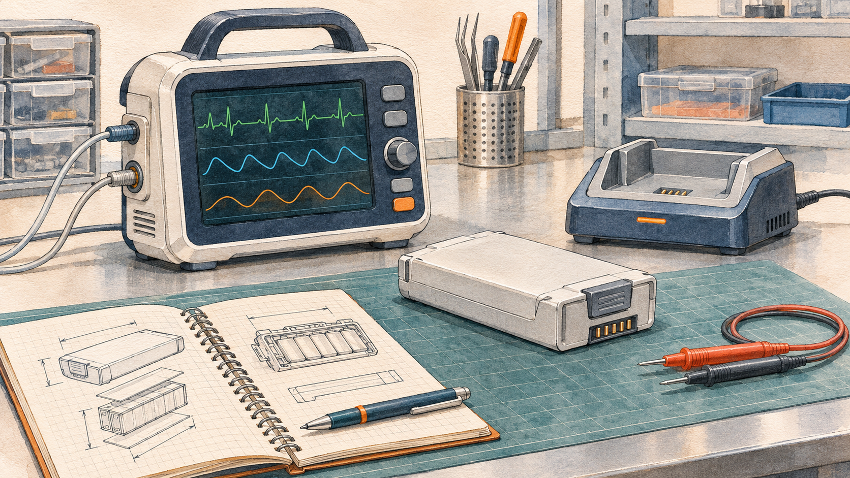
Quick Answer: Define what the medical device must do when external power is lost or battery energy runs low. Convert that behavior into measurable requirements for runtime, peak load, warning time and recovery. Then verify the production-intent battery pack, device and charger together. Before release, confirm that the supplier’s quality-system scope, test reports and change-control records cover the configuration you intend to buy.
Part 1: Define the Device Behavior Before Sizing the Pack
1.1 Identify the Functions That Must Continue
A battery specification starts with the device’s intended use. A portable patient monitor may need to maintain monitoring during a transfer between power sources. An in vitro diagnostic analyzer may need enough energy to finish a step, preserve its records or end an assay in a controlled way. A portable oxygen concentrator may need to start its compressor again late in the discharge cycle. Each case leads to a different test and acceptance criterion.
Ask the device team to describe the expected outcome in observable terms. For an analyzer, specify which assay phases can continue, when the instrument may block a new run, and what happens to results already collected. For a monitor, specify how the device should behave during transfer and what interruption, if any, is acceptable for each function. Record these decisions in the device risk-management process and trace them to verification cases. ISO 14971 medical-device risk management
1.2 Define the Warning and Required End State
A displayed state of charge is an estimate. Define the warning margin as the usable time between a specified warning and the point at which the device must have completed the required action. Record who receives the warning, what the user or device needs to do, and which functions must remain available during that interval.
Treat normal shutdown and battery protection events as separate cases. Confirm that the device can execute its planned response before the pack’s protective cutoff under the conditions you specify. Also verify the device’s response if an unexpected protection event interrupts power earlier. Battery low-charge alarm validation
Part 2: Translate Measured Loads Into a Battery Pack Specification
2.1 Size Runtime and Peak Power Separately
Record current and voltage at the device input during representative standby, active use, startup and repeated-load events. Use the energy consumed over the duty cycle to estimate runtime. Use the magnitude and duration of the load peaks, together with the minimum allowed voltage at the device input, to size the pack and its current path.
A pack can have enough nominal energy to meet a runtime target and still pull the device input below its operating limit during startup. Connector, harness and pack resistance all contribute to voltage drop. Verify the load profile at low charge and under the temperature and aging conditions called out in the device specification. For a portable oxygen concentrator, include compressor startup and repeated pulses associated with representative operating modes. Portable oxygen concentrator battery sizing
2.2 Give the Supplier Inputs They Can Design and Test Against
| Requirement | What the OEM should provide |
|---|---|
| Voltage window | Device input limits, startup threshold and measurement location |
| Load profile | Standby and active loads, peak magnitude and duration, and repetition rate |
| Runtime and reserve | Operating mode, starting condition, required operating time and reserve after warning |
| Charging | Charger and dock interfaces, recovery time, and behavior at temperature limits |
| Mechanical integration | Installation envelope, retention, connector engagement and service access |
| BMS interface | Signals or messages, update timing, and host behavior if data is missing or stale |
| Service life | Aging assumptions, replacement criteria and field-service requirements |
Compare candidate designs for usable energy, load response, charge behavior and mechanical fit under the same conditions. Record the selected cell model, pack configuration, protection thresholds and communications revision so later samples can be checked against the approved design.
Part 3: Verify the Battery, Device and Charger Together

3.1 Test the Conditions Most Likely to Expose an Integration Problem
Use traceable, production-intent samples for the verification cases used to support release. Record the pack, host and charger revisions, as well as each unit’s starting charge, temperature and conditioning. Set pass criteria before collecting results. An early prototype result can guide design changes, while a release result needs to represent the configuration that will actually ship.
| Verification case | What to observe |
|---|---|
| Startup near the lower operating charge limit | Device input voltage, peak current, startup outcome and protection events |
| Extended operation at the agreed end-of-service condition | Usable runtime and the first function or limit that ends operation |
| Low-charge warning under representative high load | Warning time, functions still available and completion of the required response |
| Transfer to or from the charger | Device interruption, charger response, alarm behavior and recovery |
| Missing or stale BMS data, where applicable | Fault indication, host response, event logging and recovery |
| Approved replacement pack, where applicable | Mechanical seating, recognition, charge behavior and correct status reporting |
3.2 Record Causes and Outcomes Separately
When a device stops, determine which event occurred first. A host undervoltage threshold, a pack protection event and a stale state-of-charge message can produce similar visible symptoms. Synchronize electrical measurements with device and BMS logs where possible. Record the warning, voltage at the device input, current, fault flags and device response on the same timeline.
Repeat relevant checks after mechanical or environmental exposure where the verification plan calls for it. If a drop or vibration case is followed by intermittent power, inspect retention and electrical interfaces and compare the post-exposure results with the baseline. Custom battery pack testing and validation
Part 4: Review ISO 13485 and the Evidence for the Specific Pack
4.1 Check the Supplier’s ISO 13485 Scope
ISO 13485 addresses quality management systems for medical devices. When a supplier presents an ISO 13485 certificate, check the legal entity, manufacturing address, certified activities, issuing body, certificate number and validity dates. Compare the scope and sites with the work on your purchase order, including any design or manufacturing activities you expect the supplier to perform. Ask which activities take place at other sites or subcontractors and how those activities are controlled. ISO guidance on medical-device standards
Follow the paperwork with a traceability exercise. Pick one sample pack and ask the supplier to trace it to the applicable cell lots, assembly records, BMS firmware and production test results. Review how deviations are authorized and how changes to cells, firmware, connectors or manufacturing sites are communicated.
4.2 Match Each Test Report to Its Purpose
| Evidence | What the OEM should verify |
|---|---|
| IEC 62133-2, where applicable | The report identifies the portable sealed secondary lithium cell or battery design tested, the edition used and the configuration covered. |
| IEC 60601-1, where applicable | The device team has assessed basic safety and essential performance for the medical electrical equipment configuration and identified relevant collateral or particular standards. |
| UN 38.3 transport evidence | The documentation identifies the lithium cell or battery design and matches the configuration intended for shipment. |
| Project verification records | The pack, charger and host revisions match the approved configuration and the results address the device requirements. |
Check the applicable editions and evidence requirements with the device and transport teams for the intended markets and shipment configuration. IEC 62133-2 · IEC 60601-1 · UN Manual of Tests and Criteria
Part 5: Release the Approved Configuration and Control Changes
5.1 Review First Articles Against the Purchase Specification
Compare first articles with the approved drawing, label, connector pinout, cell model, BMS firmware and protection settings. Check that the supplier can reproduce the identifying information on subsequent lots. Define which results must accompany each shipment and which records the supplier must be able to retrieve on request.
Keep the approved specification, device verification report, applicable safety and transport evidence, lot traceability requirements and approved deviations together. This gives engineering, quality and procurement a common reference if a later shipment shows a different label, firmware version or electrical response. Battery pack end-of-line testing
5.2 Decide What Changes Trigger Reverification
A replacement cell can change voltage sag, charging behavior or the accuracy of the remaining-runtime estimate. A firmware change can alter warning timing or protection behavior. A connector change can affect retention, electrical resistance or the device’s ability to recognize the pack. For each proposed change, identify affected requirements and risk controls, decide which tests to repeat, and approve the revised configuration before it enters production.
When requesting a quotation, share the load traces, voltage limits, required warning response, installation drawing, charger interface and target markets. Those inputs give the battery engineering team enough information to propose a pack and agree on what must be proven before shipment. Large Power medical battery solutions
FAQ
Can we select a medical-device battery pack by voltage and amp-hours alone?
The selection also depends on the voltage at the device input during load peaks, usable energy under the intended duty cycle, charging behavior, the mechanical interface and the device’s response to low battery power. Verify those requirements with the pack installed in the intended device configuration.
Which battery changes should trigger a review?
Review changes to the cell, protection settings, BMS firmware, connector, charger or manufacturing process that could affect an approved requirement. Use the device risk assessment and the scope of existing evidence to decide which checks to repeat and whether documentation needs to be updated.


