

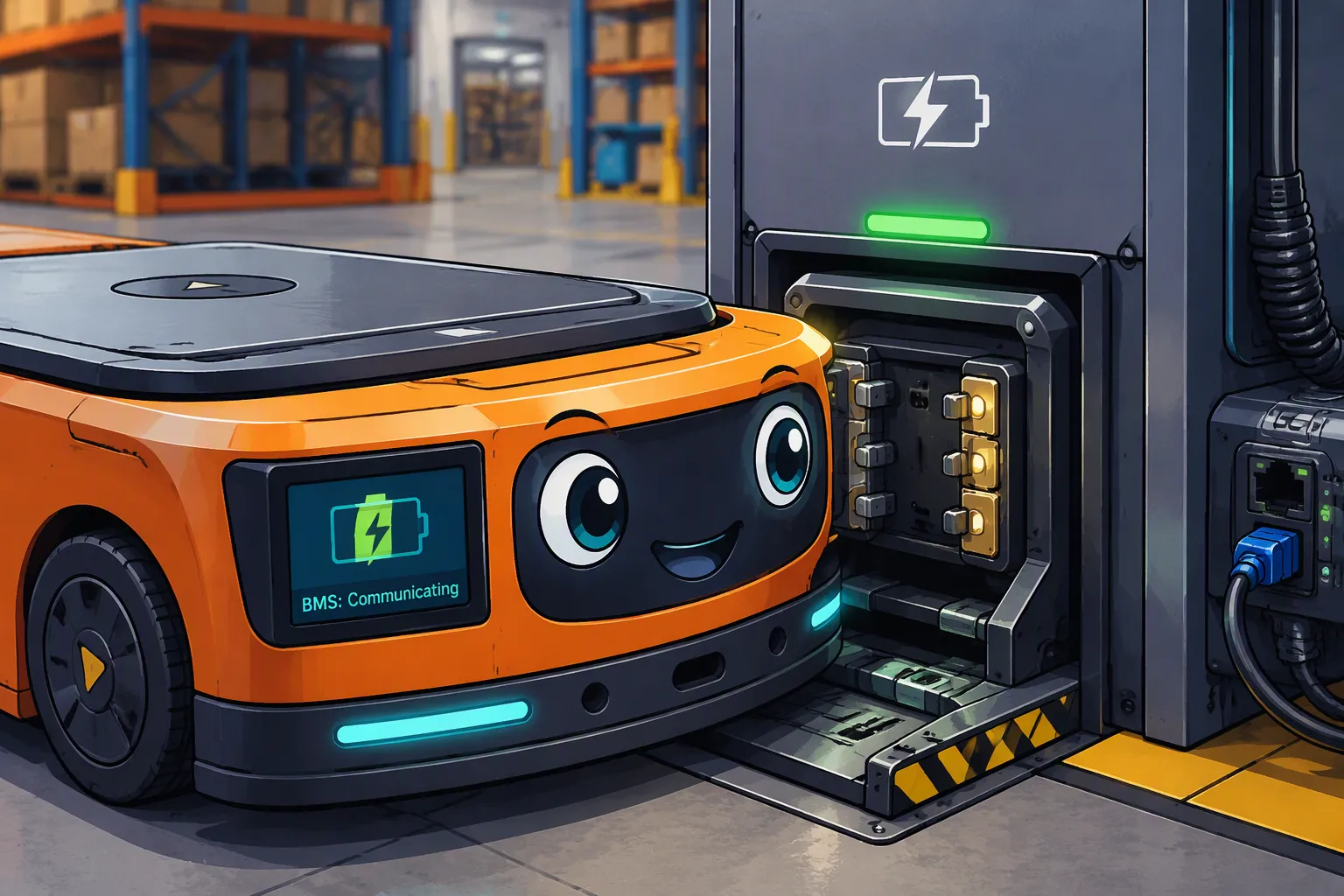
Reliable AMR charging requires the battery pack, charger, robot controller and docking mechanism to work as one system. A robot can reach the dock successfully yet fail to charge because contacts are only partially engaged, battery limits are misinterpreted or the charger and controller disagree about readiness.
For OEMs, integration starts with an interface specification and a validated operating sequence. Selecting a pack by nominal voltage or choosing a charger because it has CAN is not enough. Define electrical limits, communication behavior, contact geometry and fault responses before fleet deployment.
Quick Answer: Align the battery’s full voltage range and permitted charging current with the charger, define the BMS application protocol and timeout behavior, and validate docking tolerances and contact heating. The charger regulates charging; the BMS supplies limits and protection according to its design; the robot controller coordinates docking and motion. Verify safe start, stop and undocking under normal and fault conditions.
Key Takeaways
Distinguish a dock that supplies input power to an onboard charger from an offboard charger connected directly to the pack.
Specify messages, units, timing and failure behavior, not just CAN or RS485 hardware.
Test charging contacts at realistic misalignment, wear, contamination and current.
Determine opportunity-charging duration from usable energy and available charging windows.
Use telemetry for diagnosis and scheduling without assuming guaranteed failure prediction.
Part 1: AMR Battery and Charging Dock Integration Basics

1.1 Start with the Energy Budget and Charging Architecture
Measure the robot’s operating profile, including travel, lifting, idle electronics and auxiliary loads. Establish usable battery energy, reserve requirements and charging windows. Opportunity charging means using available idle periods for replenishment; it does not universally mean a 10–20 minute session.
As an illustrative calculation, 500 W of measured net power entering the battery for 12 minutes supplies approximately 100 Wh. Actual replenishment can be lower when charging tapers, temperature limits apply or robot loads remain active. Use pack-side measurements and avoid counting conversion losses twice.
Architecture | Control implication |
|---|---|
Dock powers an onboard charger | The dock supply must fit the charger’s input limits; onboard electronics regulate battery charging |
Offboard charger connects through dock contacts | The external charger must match pack limits and the defined enable or communication interface |
Communication-enabled dock | Presence, readiness or telemetry can be exchanged, but safety depends on the implemented controls |
A dock without a data bus is not necessarily uncontrolled. Hardware detection, interlocks and a dedicated onboard charger may form a valid architecture. Conversely, a communication link does not establish electrical compatibility or a safety-rated function by itself.
1.2 Match Navigation Accuracy to Contact Geometry
Define lateral, longitudinal, vertical and angular docking tolerances. Include floor variation, payload-related deflection and navigation repeatability. Contact compliance, engagement depth and force must maintain a qualified connection across the permitted envelope without damaging the robot or dock.
Wiping contacts can help manage some surface contamination, but do not eliminate cleaning or inspection. Specify contact material, plating, current derating, retention and replacement criteria from the actual supplier’s data. Keep alignment forces out of unsupported electrical terminals.
Part 2: DC Charging and BMS Communication
2.1 Coordinate Charger Regulation and Battery Protection
The charger controls normal current and voltage. A BMS may communicate allowable charging limits and inhibit charging when conditions are unsuitable. Protection disconnection is normally a fault response, not the routine method for terminating every charge.
Many lithium-ion systems use a cell-specific constant-current/constant-voltage profile, with reduced-current recovery only when permitted and suitable termination criteria. Do not apply indefinite trickle charging or arbitrary recovery to an over-discharged pack. Normal settings must follow the exact cells and pack specification.
Do not confuse low-current cell preconditioning with precharging system capacitance before closing a power path. The latter addresses inrush and may require a resistor, controlled switching or another engineered solution. A software handshake alone does not limit inrush or detect every electrical fault.
2.2 Define the Application Protocol and State Machine
CAN and RS485 specify different interface layers and do not make two products interoperable. Agree on message identifiers, scaling, units, byte order, update intervals, checks and firmware compatibility. Document charge enable, current and voltage limits, temperature status, faults and readiness signals where used.
State | Required design decision |
|---|---|
Approach and detection | How robot presence and permitted alignment are established |
Connection qualification | Which contact, polarity and electrical checks the hardware actually supports |
Ready to charge | Which controller grants permission and how valid limits are obtained |
Charging | Current ramp, voltage regulation, thermal supervision and limit updates |
Stop and undock | How current is reduced, power is isolated where required and release is confirmed |
Fault | Safe response, alarm, retry limits and authorized recovery |
Specify safe behavior for missing, stale, implausible or conflicting data. A charger must not continue indefinitely using an old high-current request after communication fails. Select response timing and fallback conditions through the system risk analysis rather than a generic timeout.
Prevent motion that would separate contacts carrying current unless the interface is specifically designed and validated for it. Coordinate the stop request and electrical response before undocking. Keep necessary protective functions independent of fleet-network availability.
Part 3: Mechanical Interfaces for Repeated Duty Cycles
3.1 Contact Resistance, Heating and Wear
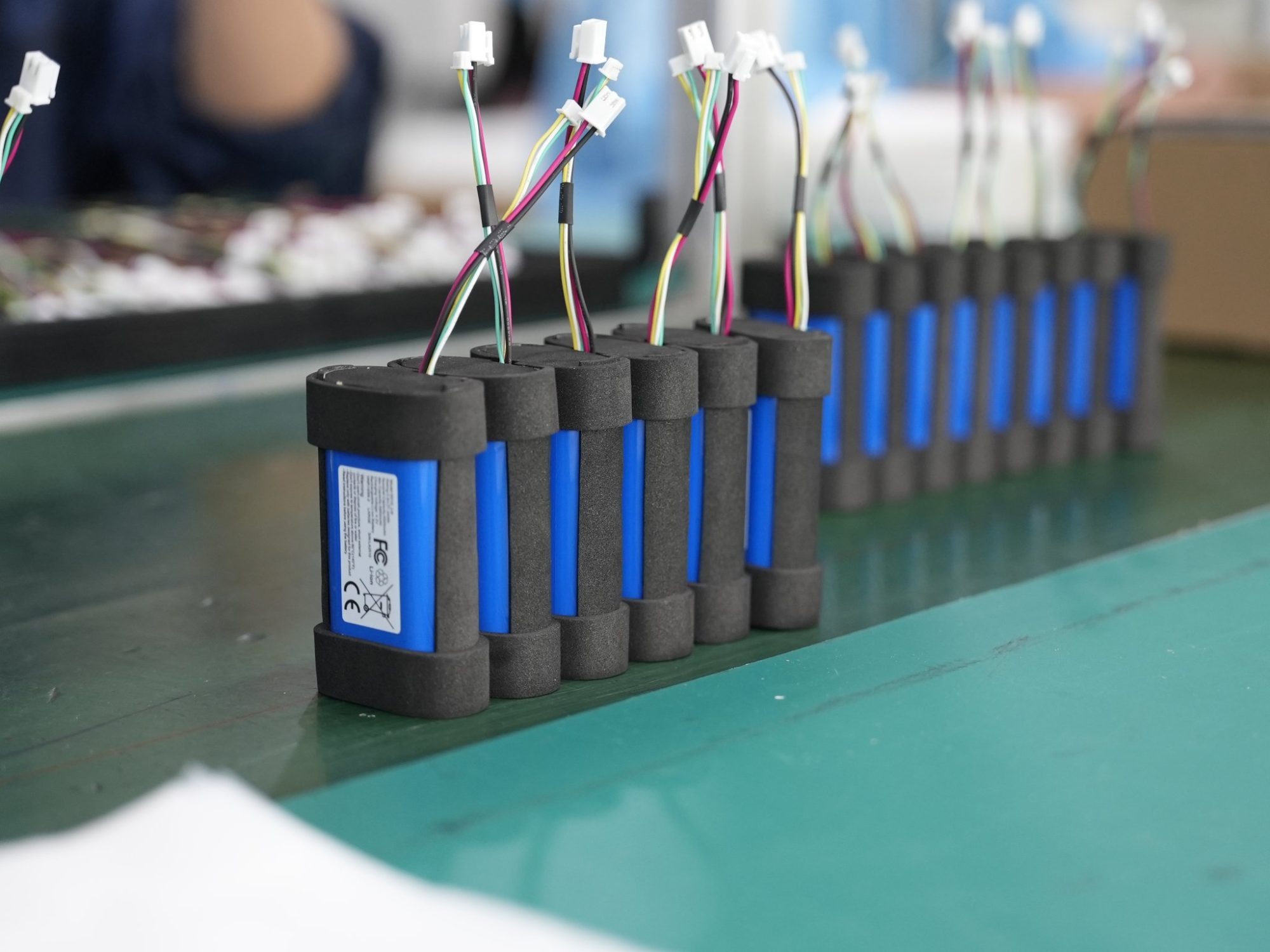
Evaluate the complete charging path: contacts, cable, terminals, switching devices and connections. Resistive heating rises with current squared. For illustration, a 5 mΩ total connection resistance dissipates 2 W at 20 A. This example is not an acceptable temperature or resistance limit.
Measure voltage drop and local temperature under representative charging current, misalignment and aged contact conditions. Include repeated docking, vibration and contamination appropriate to the site. Define acceptance limits and inspection intervals from testing and supplier guidance.
A pack BMS does not automatically measure docking-contact resistance. Detection may require voltage measurements on both sides, contact temperature sensors or dedicated diagnostics. Identify sensor coverage and blind spots rather than promising that cell temperature monitoring protects every connection.
3.2 Environmental Protection and Service Access
Indoor factories, cold stores and outdoor sites present different requirements. Assess dust, conductive debris, moisture, cleaning chemicals and condensation where applicable. Define the required ingress protection for the correct assembly and connection state; an enclosure rating does not automatically cover exposed charging contacts.
Seals and vent membranes must be selected and validated for the installation. A vent can assist pressure equalization but does not guarantee freedom from condensation or corrosion. Test enclosure temperature and contact heating with the actual airflow and expected ambient conditions.
Provide access to clean or replace wear components safely. Include isolation instructions and criteria for damaged contacts, loose terminals and degraded seals. A fleet operating continuously still needs planned servicing and a safe way to take a dock out of use.
Part 4: Fleet Telemetry, Safety and OEM Validation
4.1 Use Telemetry to Separate Energy Problems from Dock Problems
Log arrival time, docking attempts, charge-enable transitions, battery state of charge, measured current and voltage, limiting reasons, temperature and faults. Distinguish queue time, alignment time, active charging time and completed energy transfer. A robot occupying a dock is not necessarily receiving power.
Correlate robot, BMS and charger timestamps to diagnose repeated restarts or low charge power. A high state-of-charge estimate cannot replace measured charging confirmation. Validate state-of-charge accuracy and reserve logic as the battery ages.
Telemetry can support maintenance planning when linked to established thresholds and validated trends. Do not claim a universal 90-day failure forecast or guaranteed end-of-life prediction. Define what the available measurements can actually detect and assess false alarms as well as missed faults.
Choose chemistry from mass, usable energy, charge acceptance, temperature and life requirements. LiFePO4, NMC and LTO each have tradeoffs, but chemistry names do not establish a fixed cycle life or guaranteed charging duration. Qualify the chosen cells under the intended duty cycle.
4.2 Validate the Battery, Charger and Robot Together
For applicable industrial lithium batteries, IEC 62619 addresses safety requirements and tests. ISO 3691-4 addresses driverless industrial trucks and their systems, including applicable AMRs. Confirm relevant editions, regional adoption and product scope with the responsible compliance team. Neither reference alone approves an entire charging installation.
Determine charger electrical safety, EMC and installation requirements for the target market. Transport testing and battery test summaries are separate from in-use integration approval. Use testing documentation that identifies the supplied configuration and its limitations.
Validate normal charging, low and high permitted battery states, temperature-related limits, failed docking, contact bounce, communication loss, interrupted mains and controlled undocking. Check power-path transients and system-capacitance charging where relevant. Perform hazardous fault tests with qualified personnel and appropriate facilities.
Ask suppliers for interface drawings, charging specifications, application-protocol documentation, firmware versions and agreed change control. Large Power can support robot battery integration based on these requirements. Provide the charger model, docking interface, robot loads and duty cycle when requesting a custom battery solution.
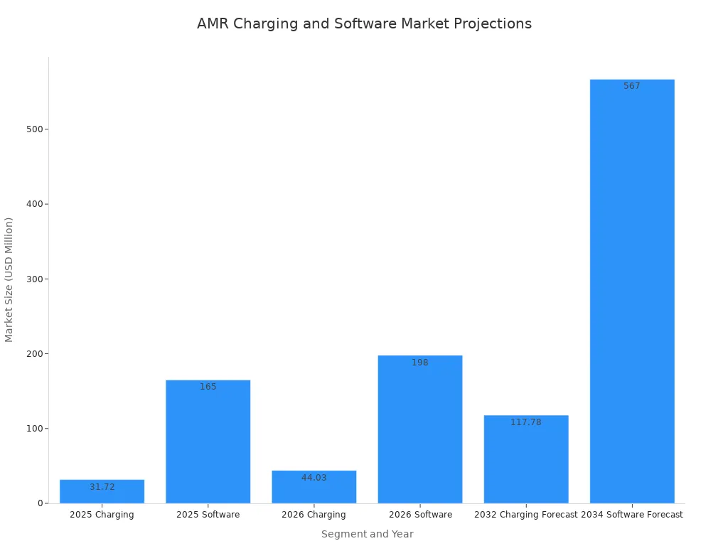
Market projections in the accompanying graphic provide background context only. They do not establish engineering requirements or predict the performance of a specific charging system; verify the original forecast sources before using its figures in commercial decisions.
Reliable charging comes from defined responsibilities and verified interfaces. Approve the pack, charger and dock as a coordinated system, then control changes to contacts, cells, firmware and charging settings so production remains consistent with the validated design.
FAQ
Does every AMR charger need direct BMS communication?
No. Some architectures use an onboard charger with defined hardware controls. Where direct communication is required, specify the application protocol, limits and failure behavior. The design must remain safe when the link is unavailable.
Does a successful handshake prove the contacts are safe?
No. It confirms only the conditions the implementation actually checks. Contact engagement, current capability and heating require mechanical and electrical validation. Detecting resistance or local overheating may need additional sensors.
How long should opportunity charging last?
Calculate it from the energy to replenish, available battery-side charging power and operating windows. Include tapering, temperature limits, robot loads and charger availability. There is no fixed duration suitable for all AMRs.
Can CAN or RS485 products be connected without further configuration?
No. Matching electrical interfaces is only the starting point. Message definitions, timing, units, addressing and fault responses must be compatible and tested.
What should happen when communication fails during charging?
The system should enter its validated fallback or stop behavior within the specified time. Define handling of stale limits, alarms, retries and recovery. Do not assume continuing with the last request is safe.
Which tests matter before fleet deployment?
Verify the assembled system’s charging behavior, contact temperature, permitted misalignment, wear, environmental exposure and fault responses. Test orderly current shutdown before undocking, and confirm that telemetry distinguishes docking from actual energy transfer.


