

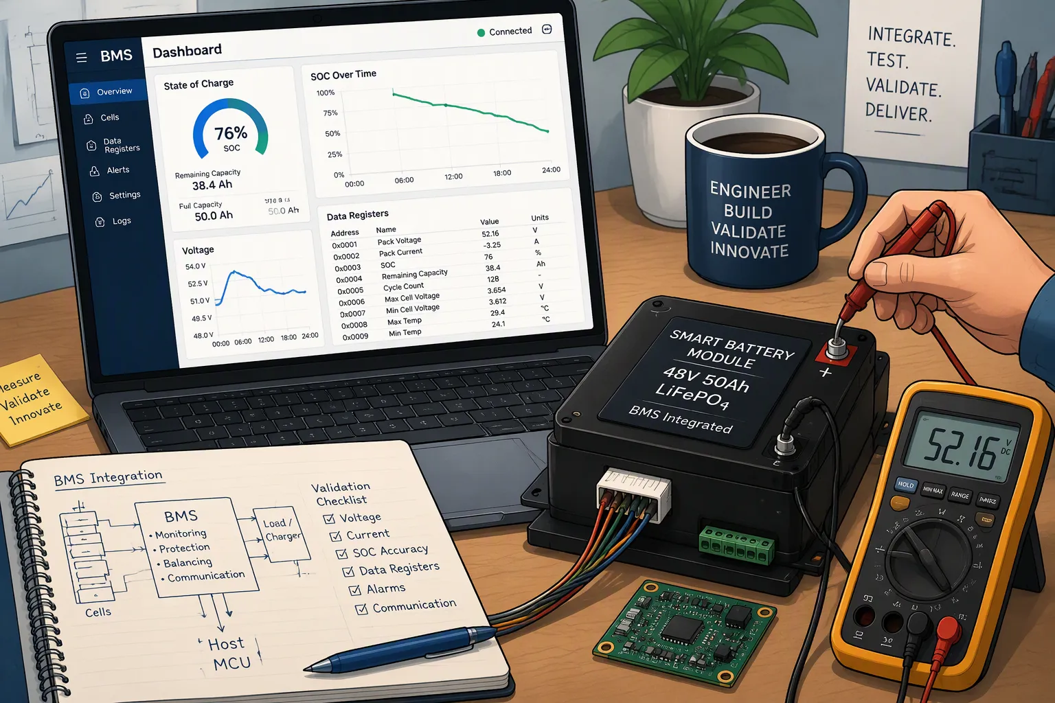
Integrating a smart lithium battery pack requires more than displaying voltage and a charge percentage. The host must interpret the pack’s data correctly, recognize when that data is stale or unavailable, and respond predictably during charging, discharge and faults. A compatible connector and a successful first read do not establish system compatibility.
Quick Answer: Agree a version-controlled interface specification before integration. Verify field definitions, units, byte order, access permissions, update rates and invalid-value handling. Validate SOC against an independent reference under defined conditions, then test host behavior during communication loss, pack replacement and protection events. Record measurable acceptance criteria and retain evidence for the evaluated hardware and firmware versions.
Key Takeaways
Separate the communication transport from the battery data model; CAN does not automatically provide an SBS register map.
Verify units, signed values, scaling, capacity mode and freshness before using telemetry for host decisions.
Specify SOC error in percentage points and validate it over relevant temperatures, loads and battery ages.
Do not treat charging requests, broadcast settings and protection switches as interchangeable commands.
Use controlled fault injection and documented pass/fail criteria; a checklist supports validation but does not itself establish regulatory compliance.
Part 1: Define the Smart Battery Interface

1.1 Separate Transport, Data Model and Host Behavior
SMBus defines communication behavior, while a Smart Battery Data implementation defines battery commands and their meaning. An I2C-compatible electrical interface does not automatically satisfy every SMBus requirement. CAN supplies a different communication framework; message identifiers, payloads and application behavior must be specified separately.
Request the actual battery interface document, not just a protocol name. Identify the connector pinout, signal levels, grounding or isolation, address or CAN identifiers, supported transactions, bus speed and startup sequence. Define which party initiates communication and whether the pack sends periodic messages, responds to polling or supports both.
For an SBS implementation, use the applicable SBS specifications alongside the gauge manufacturer’s documentation. Manufacturer-specific commands require their own definitions. For custom CAN or RS485 interfaces, obtain the approved message or register map rather than assuming compatibility from the physical bus.
1.2 Build a Controlled Data Dictionary
Field group | What to define | Host check |
|---|---|---|
Voltage, current and temperature | Measurement location, units, scaling, signedness and resolution | Compare with calibrated references at several operating points |
SOC and capacity | SOC definition, capacity units, update behavior and invalid values | Check consistency against controlled discharge results |
Status and faults | Bit meanings, severity, latching and recovery | Verify the required host response to each supported condition |
Charging information | Requested limits, charger responsibilities and command permissions | Confirm the host and charger respect both pack requests and independent design limits |
Identification | Pack model, serial number and relevant firmware or interface revision | Reject or flag incompatible variants according to the integration policy |
Check byte order and signed-current interpretation with known charging and discharging conditions. Confirm whether an API expects a 7-bit address or an address byte containing the read/write bit. Capacity values must be interpreted using the selected reporting mode; charge and energy units are not interchangeable.
Distinguish pack temperature from individual-cell temperatures. A single reported temperature does not prove that every cell is monitored. Likewise, a manufacturer-specific SafetyStatus field should not be presented as a universal standard command supported by every smart pack.
Part 2: Verify Register Behavior and Charging Responsibilities
2.1 Test Read Data Without Assuming It Is Current
Compare terminal voltage against a suitable meter, current against a calibrated measurement channel and temperature against an appropriate reference. Specify tolerance, measurement uncertainty and sampling alignment. Validate zero-current offset and both current directions; one successful reading cannot reveal a sign or scaling error across the full range.
Check the update interval and filter delay. A slowly changing capacity estimate may update in steps because of resolution or filtering. Do not require every successive sample to decrease monotonically under a small load. Instead, evaluate the integrated change over a defined interval and load profile.
The host should distinguish a valid zero from an unavailable value, a timeout and the last valid sample. Define a maximum acceptable data age for each decision. Mark stale data explicitly rather than continuing to display it as a fresh measurement.
2.2 Distinguish Read-Only Requests from Write Commands
Do not write to a command merely because its name sounds like a setpoint. In SBS, ChargingCurrent and ChargingVoltage communicate battery charging requests; they are not generic host-writable battery control registers. The BatteryMode CHARGER_MODE setting controls relevant broadcasts, not a universal command to open the charge FET. Confirm access permissions and behavior in the applicable specification and device documentation.
Test only documented writable fields using an authorized procedure. Verify supported ranges, rejected writes, reserved bits, persistence and the effect of reset. A readback difference may reflect clamping, quantization, delayed application or an access restriction, not necessarily a firmware defect. Compare the result with the documented behavior.
Validate the charging chain separately: pack request, host interpretation, charger configuration and measured output. Protection cutoff is a separate function from normal charge regulation. A working data link does not replace the pack’s protective hardware or the charger’s limits. Define what happens when charging telemetry is missing, inconsistent or out of range.
Part 3: Validate SOC Reporting Against a Reference
3.1 Define What the Percentage Represents
SOC is an estimate of remaining charge under a defined model, not a direct guarantee of remaining runtime. Relative SOC, absolute SOC, remaining capacity and full-charge capacity can have different reference bases. Host shutdown thresholds, load power and temperature further influence usable runtime.
Set an application-specific accuracy requirement. For example, a project might require an error within five percentage points over a stated SOC range and test envelope. Label this as a project criterion, not a universal requirement of IEC 62660 or SAE J2464. Specify whether the limit applies to maximum error, an average measure or particular operating regions.
Do not set learned full-charge capacity equal to nominal datasheet capacity throughout the product’s life. A gauge may update its estimate through a manufacturer-defined learning process. Confirm chemistry configuration, current calibration and learning status before interpreting capacity-based health indicators.
3.2 Use Independent Measurements and Realistic Profiles
Establish a controlled reference procedure with defined charge completion, rest conditions, discharge cutoff, temperature and current measurement. Integrate independently measured current over time and define the usable-capacity basis. Record reference uncertainty; calling a calculated value “true SOC” does not remove measurement error.
Test representative steady, pulsed and standby loads, including transitions and recovery. Cover relevant temperature limits and aged samples selected through the validation plan. Examine startup after storage, incomplete charging, long standby periods and low-SOC operation, where the host’s reserve warning may matter most.
Rested open-circuit voltage can provide a supporting plausibility check, but depends on chemistry, temperature, hysteresis and relaxation. LiFePO4’s flat voltage curve makes voltage-only SOC interpretation especially difficult over much of its operating range. Do not promise one accuracy level from an algorithm name alone.
Log reported SOC, reference estimate, voltage, current, temperature and timestamps together. Investigate jumps rather than automatically accepting or rejecting them: model corrections, changes in available capacity and configuration errors can produce different behavior. Validate the displayed reserve and actual device runtime separately from percentage accuracy.
Part 4: Validate Host Communication and Fault Responses
4.1 SMBus and I2C Tests
Use the supported protocol version and component limits to define timing and electrical checks. The official SMBus specifications are the reference for protocol requirements. Do not convert one adapter’s default timeout into the battery’s required timeout or infer a universal cable length from bus capacitance alone.
Check signal levels, rise time, loading and timing with the intended harness and pull-ups.
Verify command format, byte count, addressing and repeated-start behavior where applicable.
Test PEC generation and rejection when required or supported by the implemented interface.
Inject address NACK, data NACK, truncated messages and a controlled stuck-bus condition.
Verify bounded retries, backoff, timeout reporting and a documented recovery sequence.
PEC detects specified packet errors; it is not authentication and does not make stale or semantically incorrect data safe. Raw I2C does not inherently add SMBus PEC. Confirm how the host handles unsupported commands rather than retrying indefinitely.
4.2 CAN, Alerts and Recovery Tests
For CAN, verify bit timing, termination, identifiers, payload lengths, scaling and message periods. Check missing messages, invalid identifiers and stale payloads. Include sequence counters, application checksums or additional integrity measures only when defined by the application protocol.
Test unplugging and reconnecting separately from controlled CAN error-state testing. Disconnecting a node does not necessarily force bus-off. Use a suitable test setup to verify error-passive and bus-off handling where relevant, and follow the controller’s documented recovery behavior. Reconnection alone is not proof that every recovery path works.
Verify an alert pin or event notification only if the design supports it. Define assertion, acknowledgment, latching, clearing and polling fallback. Use a simulator or approved sensor-signal injection for initial fault tests instead of deliberately overheating or overcharging a live pack. Physical protection tests require a controlled, suitably equipped procedure.
Communication loss should lead to a risk-assessed system response, not a universal immediate shutdown. Depending on the device, the response may include an alarm, charging inhibition, a restricted operating mode or a controlled transition to another power source. Validate that response at system level, including pack removal, insertion, sleep, wake and host reset.
Part 5: Turn the Results into a Release Checklist
5.1 Define Measurable Acceptance Criteria
Check | Evidence to record | Acceptance basis |
|---|---|---|
Data interpretation | Raw bytes, decoded values, reference readings and units | Approved interface map and measurement tolerances |
Freshness | Update interval, missing-message duration and host indication | Maximum age allowed for each host function |
SOC | Reference method, error versus time, load, temperature and sample condition | Defined percentage-point error and operating envelope |
Charging | Battery request, host command, measured charger output and fault response | Approved charging limits and loss-of-communication policy |
Fault recovery | Injected event, detection time, retries, host action and recovery | System requirements and risk controls |
Configuration | Pack serial number, hardware, firmware, parameter and host software revisions | Approved release configuration |
Use pass, fail, blocked and not-applicable outcomes with documented reasons. A blocked test must not become a pass because the equipment or evidence was unavailable. Record deviations, investigation, corrective changes and retest results. Escalate to the formal quality process when required; not every integration issue automatically needs a full CAPA.
5.2 Control Changes and Separate Qualification from Production Testing
Retain the interface document, test scripts, calibrated-equipment records and raw logs with the evaluated revisions. Assess changes to gauge firmware, chemistry configuration, protection settings and host software. Select regression tests based on the affected functions and risk, rather than assuming either that no retesting is needed or that every change requires complete requalification.
Integration qualification differs from battery pack end-of-line testing. Production checks can verify identification, basic telemetry and defined functions, but do not replace temperature, aging or system fault validation. Likewise, passing communication tests does not establish all medical-device or industrial safety requirements.
For a custom smart battery project, share the host interface, load profile, charging architecture and required fault responses with Large Power early. Agree which features the BMS or PCM actually implements and which must be handled by the host. Release should rest on traceable evidence, not merely a successful demonstration.
FAQ
Does every smart battery use the same register map?
No. SBS-compatible packs implement a defined command model, but supported extensions and device behavior still need verification. Custom CAN and RS485 packs require their own interface documentation.
Can the host write ChargingCurrent to switch charging off?
Do not assume so. An SBS charging request is not a generic writable switch command. Verify the pack and charger documentation, supported control commands and the intended charging architecture.
What SOC accuracy should an OEM require?
Set the requirement from the application, including operating conditions, age, reference method and allowed error in percentage points. There is no single accuracy target that every smart battery must meet.
Does a CAN disconnection prove bus-off recovery?
No. Cable disconnection and bus-off are different test conditions. Validate link-loss handling and the controller’s documented error-state recovery using appropriate test methods.
What should happen when battery data stops updating?
The host should detect stale or missing data and follow its validated response policy. Do not continue to treat the last reading as current. The appropriate response depends on the device and its risk analysis.
Should fault tests deliberately overheat the battery?
Not for routine host-interface validation. Start with a simulator or approved signal injection. Any physical abuse or protection qualification must use a separately controlled safety procedure.


