

Quick Answer
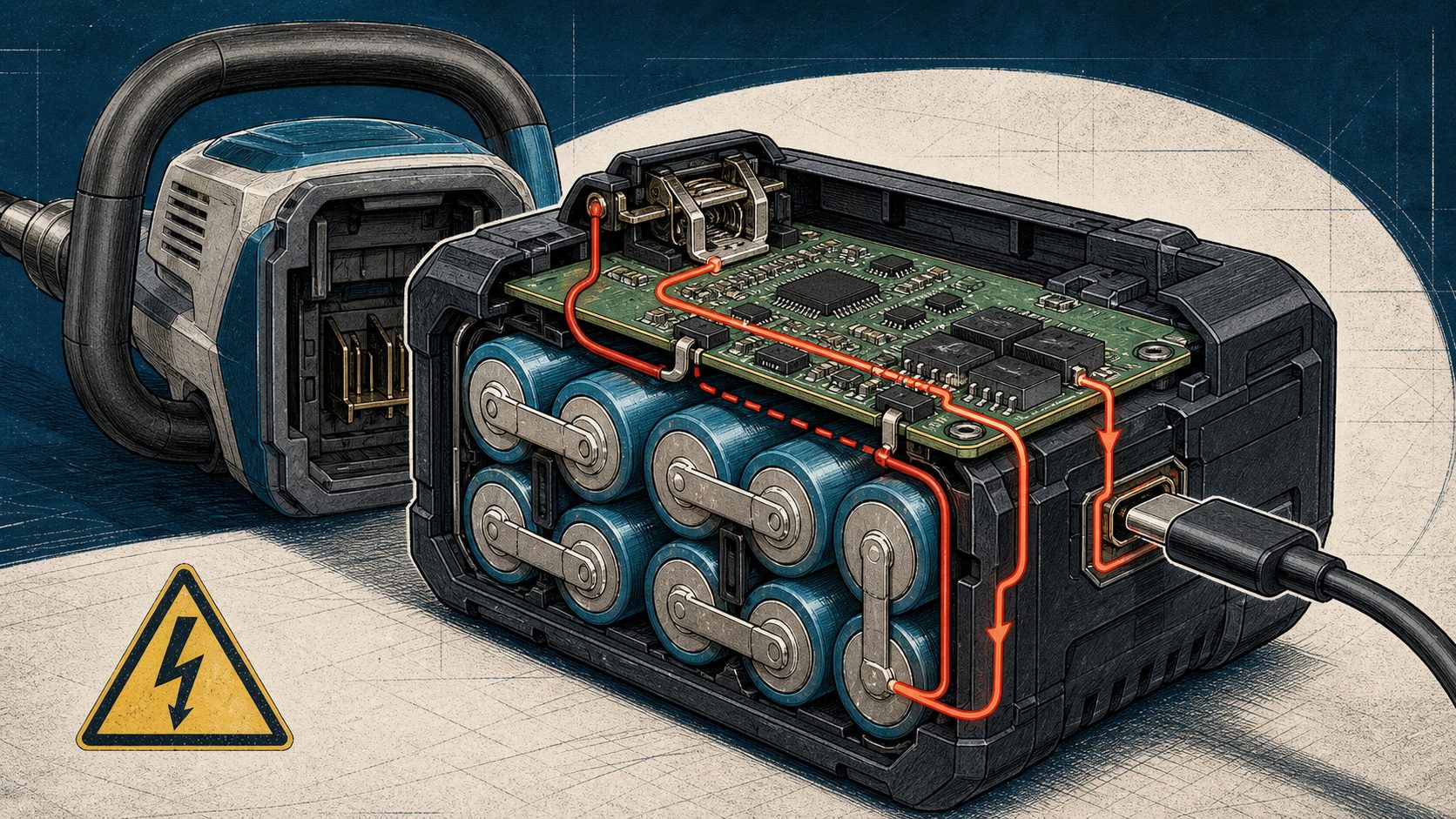
The 2026 Greenworks Kobalt battery recall shows why manufacturers must validate the battery, BMS, USB-C charging circuit, host equipment, connectors, and protection logic as one complete system. The official recall does not identify the BMS as the sole cause. It states that affected batteries can short-circuit when charged through the USB-C port while installed in certain yard tools. For battery manufacturers, the incident highlights the importance of coordinated protection, charging-path isolation, fault testing, and system-level validation.
Part1: Greenworks Kobalt Battery Recall Overview
1.1 What Happened in the 2026 Recall
On July 9, 2026, Greenworks Tools recalled certain Kobalt 24V and 48V yard power tools supplied with USB-C lithium-ion batteries. According to the U.S. Consumer Product Safety Commission, charging an affected battery through its USB-C port while the battery remains installed in the tool can cause a short circuit, creating a serious fire hazard.
The recall covers approximately 554,780 products, including selected Kobalt trimmers, blowers, mowers, chainsaws, and pruning saws. Some affected 48V tools operate with two 24V batteries.
Greenworks received 34 reports of batteries smoking, sparking, or catching fire while installed in a tool and charging through USB-C. No injuries or property damage had been reported when the recall was announced.
1.2 The USB-C Charging Hazard
The hazardous condition described in the recall involves a specific operating configuration:
- The lithium-ion battery remains installed in the yard tool.
- A USB-C charging cable is connected to the battery.
- The battery is charged through its USB-C port.
- The battery can short-circuit, potentially producing smoke, sparks, or fire.
Consumers were instructed to stop charging the affected batteries through USB-C while the batteries were installed in the tools. The recall remedy includes replacement batteries without USB-C ports, charging adapters where applicable, updated manuals, warning labels, and instructions for returning the recalled batteries.
Removing the USB-C port from the replacement battery eliminates the affected charging configuration and reduces charging-path complexity.
1.3 What the Official Recall Does Not Establish
The public recall notice does not identify the BMS, USB-C controller, connector, tool circuitry, or any other individual component as the confirmed root cause.
Manufacturers should therefore avoid describing this incident as a proven “BMS failure.” A more accurate interpretation is that the event demonstrates the risks that can appear when a battery, charging interface, and host device interact under a particular operating condition.
Identifying the technical root cause would require information that is not included in the public announcement, such as circuit diagrams, component-failure analysis, protection settings, firmware behavior, and test results from affected products.
The engineering lesson is broader than any single component: battery safety is a system-level responsibility.
Part2: Why BMS and Charging-Path Design Matter
2.1 Multiple Current Paths in Tool Batteries
A removable power-tool battery may interact with several electrical paths:
- The primary discharge connection between the battery and tool
- A dedicated external charger connection
- A USB-C charging or power-delivery circuit
- Battery communication and identification terminals
- Temperature-sensing circuits
- Tool-side capacitors and power converters
- Motor-control and switching electronics
Each path may function correctly when evaluated independently. Unsafe conditions can still appear when multiple paths become active at the same time.
Charging through USB-C while the battery remains connected to the tool can create conditions that do not exist during standalone charging. Depending on the electrical architecture, engineers may need to evaluate reverse current, unintended current loops, shared grounds, connector sequencing, stored energy in the tool, and abnormal switching states.
Charging safety should therefore be validated in every permitted product configuration.
2.2 The Role of the Battery Management System
A properly engineered Battery Management System monitors critical battery conditions and controls charging and discharging when necessary.
Depending on the application, BMS functions may include:
- Cell overvoltage and undervoltage protection
- Charge and discharge overcurrent protection
- Short-circuit protection
- Cell and component temperature monitoring
- Charge and discharge MOSFET control
- Cell balancing
- State-of-charge estimation
- Fault recording
- Communication with the charger and host equipment
These functions help reduce battery risk, but a BMS cannot automatically compensate for every system-design problem. Its protection thresholds, response time, MOSFET arrangement, current-sensing position, temperature-sensor placement, and firmware logic must match the complete electrical architecture.
If USB-C introduces an additional charging path, engineers must confirm that the BMS can monitor and interrupt abnormal current through that path. A fault path that bypasses the main current sensor or protection switch may not produce the expected protective response.
The Greenworks Kobalt recall does not prove that such a bypass occurred. It shows why engineers must include every possible charging and discharge path in their safety analysis.
2.3 Why USB-C Adds Design Complexity
USB-C improves convenience, but it adds components and operating states to a battery system. A USB-C charging design may include:
- A USB-C connector
- Configuration-channel circuitry
- A USB Power Delivery controller
- DC-DC conversion components
- Additional switching devices
- Firmware-controlled power negotiation
- Electrostatic-discharge protection
- Input overvoltage and overcurrent protection
Engineers must understand how these components interact with the primary battery terminals, the BMS, and the host equipment.
Important design questions include:
- Can USB-C be used while the battery is connected to a load?
- Is the USB-C charging circuit isolated from the main discharge path?
- Can current flow backward from the tool into the charging circuit?
- What happens if the tool attempts to start during charging?
- Does the BMS monitor current through every charging path?
- Can a partially inserted connector create an abnormal state?
- What happens if USB Power Delivery communication is interrupted?
- Can one battery affect another in a dual-battery tool?
- How does the system respond to an incorrect adapter or damaged cable?
USB-C charging should be included in the initial hazard analysis rather than added near the end of product development as a convenience feature.
Part3: System-Level Battery Validation
Battery qualification and complete-system qualification are related but different activities. A cell can pass its required tests, and a battery pack can pass standalone protection tests, while the integrated product still contains an unsafe interaction.
Manufacturers should validate the product at multiple levels.
3.1 Cell-Level Validation
Cell selection should reflect the application’s actual electrical and environmental demands. Engineers should verify:
- Cell capacity and consistency
- Internal resistance
- Peak and continuous current capability
- Charging limits
- Operating-temperature range
- Cycle-life behavior
- Lot traceability
- Performance under the intended load profile
A cell that performs adequately in a low-current application may not be suitable for a power tool with high startup or motor-stall current.
3.2 Battery-Pack Validation
The complete battery pack should be tested for:
- Overcharge and over-discharge
- Charge and discharge overcurrent
- External short circuits
- Cell imbalance
- Abnormal temperatures
- Connector overheating
- Vibration and mechanical impact
- Water, dust, and contamination where applicable
- Foreseeable misuse
- Protection-component failure
Battery testing should cover both normal operation and fault conditions. Testing only at room temperature and with a standard load may fail to reveal problems that appear under high current or environmental stress.
3.3 Charger and Interface Validation
Every supported charging method requires validation. This includes dedicated chargers, USB-C inputs, adapters, cables, charging docks, and in-tool charging configurations.
Testing should evaluate:
- Correct and incorrect adapters
- Maximum and minimum input voltage
- Interrupted charging
- Repeated connection cycles
- Partial connector insertion
- Connector contamination or wear
- Reverse current
- Charging at temperature limits
- Communication failure
- Switching-component failure
If a product provides multiple charging methods, engineers must also evaluate interactions between those methods.
3.4 Host-Equipment Validation
Battery packs should be tested while installed in the final tool or device. The validation plan should reproduce:
- Standby operation
- Normal charging
- Charging while installed
- Equipment startup
- Peak-load operation
- Motor-stall conditions
- Normal and emergency shutdown
- Battery installation and removal
- Communication interruptions
- Unexpected user sequences
- Single-component faults
Dual-battery products require additional evaluation. Engineers should consider pack imbalance, differences in state of charge, current sharing, communication between battery positions, and possible current flow from one battery to another.
Passing a standalone battery test does not remove the need for host-system testing.
Part4: Engineering Controls for Safer Charging
4.1 BMS Design Questions Manufacturers Should Ask
A BMS design review should answer the following questions:
| Design question | Why it matters |
|---|---|
| Does every charging path pass through monitored protection? | An unmonitored path may prevent timely fault detection. |
| Can charge and discharge switches be controlled separately? | Independent control may be necessary during abnormal conditions. |
| Where is battery current measured? | Sensor placement determines which current paths the BMS can detect. |
| Are temperature sensors located near critical cells and components? | Poor placement can delay temperature protection. |
| What happens if a MOSFET fails short or open? | A single protection-component failure should not create an uncontrolled hazard. |
| Can the host equipment feed current back into the battery? | Reverse current may create unexpected electrical stress. |
| Can the battery detect incompatible equipment or chargers? | Identification and communication can prevent unsafe combinations. |
| Are faults recorded and communicated? | Diagnostic data supports maintenance and root-cause investigations. |
| Has the BMS been tested with the final charger and host equipment? | Standalone BMS testing cannot reveal every system interaction. |
For high-current systems, engineers should also consider busbar resistance, fuse coordination, connector heating, current sharing, and thermal propagation between cells.
4.2 Independent Hardware and Software Protection
Manufacturers should use multiple layers of protection rather than relying on one software function or protection component.
Possible controls include:
- Hardware overvoltage and undervoltage protection
- Independent charge and discharge current limits
- Short-circuit detection
- Temperature-based charging restrictions
- Thermal fuses or current-interrupt devices where appropriate
- Charger-side voltage and current regulation
- Host-device shutdown logic
- Mechanical barriers and flame-resistant materials
- Properly rated connectors, busbars, and wiring
Firmware-controlled protection can improve flexibility and diagnostics, but independent hardware protection can provide another response layer when communication or software behaves unexpectedly.
4.3 Connector, Fault and Misuse Testing
Connectors are part of the battery safety system. Testing should include:
- Full and partial insertion
- Repeated insertion cycles
- Bent, worn, or contaminated contacts
- Water or conductive debris
- Cable damage
- Incorrect adapters
- Charging while the equipment is active
- Battery removal during charging
- Simultaneous load and charging conditions
- User actions performed in an unexpected sequence
If charging while the battery is installed is not supported, the preferred design is to prevent or electrically block that condition where practical. A warning label alone is less reliable than an engineered control.
4.4 Production Traceability and Field Monitoring
Effective traceability allows manufacturers to identify affected products more precisely if a field problem occurs.
Records may include:
- Cell manufacturer and production lot
- BMS hardware revision
- Firmware version
- Protection thresholds
- MOSFET and control-component lots
- Connector supplier
- Battery assembly date
- End-of-line test results
- Product serial number
- Warranty and field-failure records
Field data can also reveal patterns that are difficult to reproduce during development. Unexpected temperature events, repeated protection activation, charger errors, and abnormal current should be investigated before they develop into larger safety problems.
Part5: Lessons for Battery Manufacturers
5.1 Five Lessons from the Greenworks Kobalt Recall
The most important lesson from this incident is that battery safety is a property of the complete product system.
A battery interacts with the charger, host device, connectors, software, environment, and user. Adding another charging interface changes that system and introduces additional fault combinations.
Manufacturers should take five lessons from the recall:
- Do not treat USB-C as a simple connector upgrade.
USB-C creates additional power states, control components, and possible current paths. - Validate charging while the battery is installed in the final equipment.
Standalone battery testing may not reveal interactions with tool-side circuitry. - Confirm that the BMS monitors every current path.
Protection is effective only when abnormal current can be detected and interrupted. - Test foreseeable misuse and abnormal operating sequences.
Users may connect power while equipment is active, partially connected, contaminated, or damaged. - Reduce unnecessary design complexity.
A simpler charging architecture can reduce the number of failure modes that must be controlled.
The recall remedy replaces affected batteries with versions that do not have USB-C ports. This does not establish the technical root cause, but it demonstrates one risk-reduction strategy: eliminating the operating path associated with the reported incidents.
5.2 Building Safer Custom Battery Systems
Reliable custom lithium battery packs require coordinated electrical, mechanical, thermal, and software engineering. The cells, BMS, charging method, connectors, communication protocol, host equipment, and operating environment must be considered together.
For industrial equipment, medical devices, robotics, security systems, and other demanding applications, battery development should include:
- Application-specific hazard analysis
- Cell and component traceability
- BMS and PCM design
- Charger and host-device compatibility
- Thermal and mechanical protection
- Fault-injection testing
- System-level validation
- Applicable safety and transport testing
- Production quality controls
- Field monitoring and incident-response planning
These measures cannot eliminate every possible failure. They can reduce risk, improve product reliability, and help manufacturers identify unsafe interactions before large-scale deployment.
FAQ
Was the 2026 Greenworks Kobalt recall caused by a BMS failure?
The official recall does not identify the BMS as the sole cause. It states that affected batteries can short-circuit when charged through the USB-C port while installed in certain yard tools. Determining the root cause would require technical information that is not included in the public recall notice.
Why is a BMS important in USB-C battery charging?
A BMS monitors battery voltage, current, and temperature and can disconnect charging or discharging when unsafe conditions occur. When USB-C creates an additional charging path, engineers must ensure that the BMS can detect and interrupt faults through that path.
Can a battery be safe by itself but unsafe inside a tool?
Yes. A standalone battery may pass its tests while an interaction with the charger, host circuit, connector, firmware, or another battery creates an unexpected fault. Complete system-level testing is therefore necessary.
What should manufacturers test when adding USB-C charging?
Manufacturers should test standalone and in-device charging, reverse current, simultaneous loads, interrupted connections, incorrect adapters, connector damage, abnormal temperatures, communication failures, partial insertion, and protection-component faults.
Is removing USB-C always the best solution?
Not necessarily. USB-C can be integrated safely when its charging path, components, protection logic, and interaction with the host equipment are properly designed and validated. Removing it simplifies the architecture, but the correct approach depends on the application and risk assessment.
How can manufacturers improve lithium battery safety and reliability?
Manufacturers should combine qualified cells, appropriate BMS and PCM design, independent protection, thermal management, connector validation, traceability, and system-level testing. Every approved charging and discharge configuration should be included in the validation plan.
Need engineering support for BMS architecture, charging-path protection, or complete battery-system integration? Contact Large Power’s battery engineers to discuss your application requirements.


