

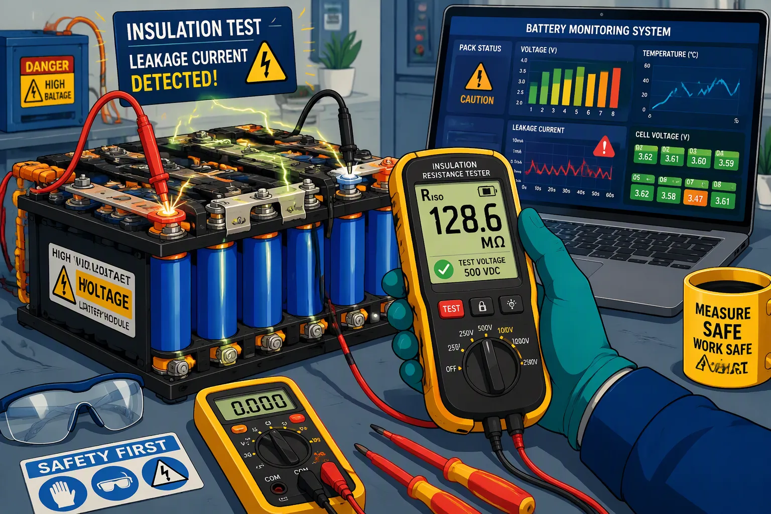
Isolation monitoring helps detect deterioration of the electrical insulation between a high-voltage battery circuit and its conductive enclosure or chassis. In a floating DC system, the monitoring device estimates insulation resistance rather than simply measuring current in a ground wire. Its usefulness depends on the measurement method, the connected equipment and a validated fault-response strategy.
Moisture, conductive contamination, damaged cables and compromised feedthroughs can reduce insulation resistance. An insulation alarm provides evidence of a problem that needs assessment; it does not identify every internal cell defect or guarantee advance warning of thermal runaway.
Quick Answer
For a high-voltage lithium battery pack, select an insulation monitoring device compatible with the maximum working voltage, grounding arrangement, leakage capacitance and operating states. Validate both single-pole and symmetrical faults, connect reliable status information to the BMS, and define warnings, start inhibition and shutdown actions through the system safety analysis.
Key Takeaways
Distinguish insulation resistance monitoring from residual-current sensing, cell-voltage monitoring and internal short-circuit detection.
Set thresholds from the applicable equipment requirements and actual circuit topology; 500 ohms per volt is not a universal rule for every battery pack.
Check the monitored boundary with contactors open, closed, during pre-charge and during charging.
Validate measurement accuracy and response time with the actual bus capacitance, switching noise and connected loads.
Treat moisture-related resistance loss as a potential real fault, even if the reading improves after drying.
Part 1: What Isolation Monitoring Detects
1.1 Define the Electrical Boundary
Start by identifying the HV positive rail, HV negative rail, enclosure, chassis bonds and protective-earth connections. A floating or unearthed system has no intentional low-resistance connection between its live conductors and earth. An insulation monitoring device, or IMD, assesses the resistance between those conductors and the reference chassis or earth.
Insulation monitoring is not the same as galvanic isolation of a communication interface. An isolated CAN transceiver can protect a low-voltage communication boundary, but it does not measure the resistance between the traction or equipment bus and the enclosure.
Draw the actual circuit and mark which components are electrically connected to the monitor in every operating state. An IMD on the battery side of open contactors may assess the pack but cannot necessarily assess a disconnected inverter, cable or charger. Conversely, a load-side monitor may lose access to the battery when those contactors open.
1.2 Insulation Faults and Their Limits
Common causes include cable abrasion, contamination around HV connectors, cracked insulating supports, coolant or water ingress and conductive residues near terminals. A cell electrolyte leak may also affect insulation if it creates a path to the enclosure, but the effect depends on the physical design and where the liquid travels.
A first fault in a floating system may produce little steady current because the return path is limited. That does not make it harmless. A second fault on the opposite rail, personnel contact or a changed grounding connection can complete a dangerous circuit. Fault progression is not predictable from resistance alone.
Isolation monitoring cannot reliably detect a separator defect or an internal cell short that does not create a path to the chassis. Temperature, voltage, current and other diagnostics remain separate protection functions. Do not describe the IMD as a thermal-runaway predictor.
Part 2: Resistance, Thresholds and Measurement Quality
2.1 Interpret Resistance Without Oversimplifying Leakage
For a known resistive path, Ohm’s law relates the voltage across that path to its current. In a floating HV system, however, the voltage from each rail to chassis depends on both insulation paths and other circuit elements. Dividing total pack voltage by one reported resistance does not automatically give the actual touch current or leakage current in every state.
Use consistent definitions for positive-to-chassis resistance, negative-to-chassis resistance and any combined resistance reported by the IMD. Confirm whether the instrument reports a parallel equivalent or separate rail estimates. Otherwise, the same number can be interpreted differently by the monitor, BMS and service team.
System capacitance and converter switching also create displacement currents. These currents differ from a persistent resistive leakage path. The monitor must distinguish them within its specified operating range; filters alone do not make an unsuitable measurement circuit reliable.
2.2 Set Application-Specific Thresholds
IEC 61557-8 addresses insulation monitoring devices for unearthed systems. It is a monitor standard, not a universal battery-pack trip-setting table. Choose the applicable equipment and market requirements separately.
For vehicle applications, UN Regulation No. 100 distinguishes separate DC and AC buses and galvanically connected arrangements. The familiar 100 ohms/V and 500 ohms/V values belong to specified configurations, with additional conditions and exceptions. Confirm the applicable amendment series and approval requirements rather than copying one value into industrial or stationary-storage designs.
If a design requirement is 500 ohms/V and the relevant working voltage is 800 V, the arithmetic gives 400 kilohms. This is an illustrative calculation, not a recommended universal trip point. Use the voltage definition required by the applicable provision, not nominal voltage by default.
Define a warning level, protective-action level, hysteresis and maximum permitted response time. Include measurement uncertainty, environmental variation and system tolerance. A fixed pack target of 1.5 megohms, without these conditions, is not a complete specification.
2.3 Separate Online Monitoring from Offline Tests
An online IMD operates with the installed HV system and its connected electronics. An offline insulation-resistance tester applies a specified test voltage under a controlled test procedure. A dielectric withstand test evaluates a different property again. These functions should not be presented as interchangeable.
Do not claim that online battery monitoring normally injects a 500 V test signal. Test voltage, injected signal amplitude and coupling method are design-dependent. Before offline testing, follow the approved isolation and connection procedure so that BMS circuits, surge components and filters are not exposed to an unsuitable test voltage.
Part 3: Selecting a Monitoring Method
3.1 Active Measurement and Switched-Resistor Methods
Active monitoring applies a controlled measurement signal and evaluates the circuit response. Switched-resistor bridge approaches compare readings in different known circuit states. Select the method around the available bus voltage, required fault coverage, acceptable measurement influence and response time.
For a concrete implementation example, TI’s TIDA-010232 reference design describes an insulation-monitoring analog front end for high-voltage EV charging and solar applications. A reference design provides a starting point; its demonstrated performance does not certify a complete battery system.
Review resistor working-voltage ratings, dissipation, tolerance, switching-device ratings, ADC inputs, protection and measurement isolation. Validate the full measurement range, including the high-resistance region and values near each decision threshold. Ask how the circuit behaves when bus voltage is low or absent.
3.2 Symmetrical Faults and Passive-Method Limitations
A voltage-unbalance method observes changes in the rail-to-chassis voltages. It can indicate an asymmetrical fault, but similar resistance reductions on both rails may leave the voltage balance largely unchanged. A balanced voltage reading therefore does not prove healthy insulation.
Both symmetrical and asymmetrical fault coverage should be checked for an IMD. Bender’s technical explanation of insulation monitoring discusses why the measurement principle must match the system. Do not assume that a rail-voltage sensor or residual-current sensor provides the same coverage.
Where multiple monitoring devices become connected during charging or contactor changes, assess possible interference between their measurement signals. Define which device is active, how control transfers and how the system verifies that no required interval remains unmonitored.
3.3 Capacitance and Switching Interference
Capacitance from the HV circuit to chassis includes cable and component parasitics and EMC capacitors. Its effect depends on the selected measurement method. Larger capacitance may increase settling time or alter the signal response; neither AC injection nor another method is universally immune.
Use the monitor’s specified capacitance range and response-time conditions as selection criteria. Test with the inverter operating, charger connected, DC/DC converter enabled and pre-charge transitioning. Evaluate worst-case accuracy and detection time, not only a quiet bench measurement.
Part 4: BMS Integration and Fault Response
4.1 Data, Diagnostics and Self-Checks
The BMS should receive resistance or fault status together with measurement validity, timestamp and monitor diagnostics. An old healthy reading must not silently remain valid after the sensor stops communicating.
Specify behavior for missing chassis connections, disconnected sense leads, auxiliary-power loss, implausible readings and communication timeouts. Self-tests and redundant checks should follow the actual safety concept. Two channels alone do not demonstrate an ASIL rating, and an automotive classification does not automatically apply to industrial equipment.
A system-level insulation alarm identifies a monitored circuit problem; it does not necessarily locate the failed cell or connector. Locating a fault may require sectional isolation, approved service measurements or dedicated fault-location equipment. Keep fault-location claims consistent with the installed hardware.
4.2 Start Inhibition, Warnings and Controlled Shutdown
Define responses for startup, normal operation, charging and service. An unacceptable result before startup may inhibit contactor closure. A developing fault during operation may require an alarm, controlled load removal or immediate protective action, depending on the hazard assessment and applicable requirements.
Opening contactors does not remove the voltage within the battery, guarantee that welded contacts open or immediately discharge downstream capacitors. Verify contactor feedback, DC-link voltage and discharge behavior. Service access must follow the equipment’s established de-energization procedure.
Coordinate the IMD with pre-charge control, contactor diagnostics, high-voltage interlocks and overcurrent protection. Reducing power is not a general remedy for a defective insulation barrier. Confirm that the chosen action achieves the required safe state and that an unsafe reset cannot restore operation.
Part 5: Verification for the Actual Battery System
5.1 Build a Fault-Injection Test Matrix
Use a controlled fixture and appropriately rated components to simulate faults. Record the resistance applied, bus voltage, capacitance, operating state and expected decision. Define limits before testing so that a result cannot be accepted simply because an alarm eventually appeared.
Test Condition | What to Verify |
|---|---|
Positive rail to chassis | Resistance accuracy, alarm level and response time |
Negative rail to chassis | Equivalent coverage on the opposite rail |
Similar faults on both rails | Detection despite limited voltage unbalance |
Threshold boundary | Repeatability, tolerance, hysteresis and reset behavior |
Maximum specified capacitance | Settling time, validity flags and detection deadline |
Monitor power or communication loss | Diagnostic coverage and defined system response |
Contactors open, closed and pre-charge | Actual monitored boundary and state transitions |
Charging and converter operation | Noise susceptibility and monitor coordination |
5.2 Humidity, Mechanical Stress and Serviceability
Validate after relevant humidity, condensation, vibration and temperature exposure using the product’s intended operating conditions. Inspect connectors, seals, insulation supports and conductive residues. Compare results before, during and after exposure where the procedure permits.
A resistance drop caused by moisture is a real electrical change, even if dry insulation material remains intact. Do not dismiss it as a false alarm merely because the resistance recovers after drying. Investigate ingress, contamination and measurement interference independently.
Keep software filtering within the allowed detection time. Validate intermittent faults, rapid degradation and reset conditions. Production and service tests should retain the pack identifier, hardware revision, firmware version, monitor settings and relevant test evidence.
For custom lithium battery packs, agree on the monitored circuit, IMD interfaces, enclosure bonding and protective actions early in development. Pair the pack specification with a system validation plan; the testing and certification process should confirm the scope of each test rather than imply that one component certifies the complete equipment.
FAQ
Is 500 Ohms per Volt Required for Every HV Battery?
No. The requirement depends on the application, grounding arrangement, connected AC and DC circuits and applicable standard. Determine the correct working-voltage basis and safety margin before setting warning or shutdown thresholds.
Can the Monitor Detect a Fault with Both Contactors Open?
It depends on where the monitor is connected and how it is powered. A pack-side monitor may assess the battery while excluding disconnected loads. Some methods need a minimum bus voltage. Validate the required coverage in each state.
Are Humidity-Related Alarms Harmless?
No. Moisture can create a conductive surface path and genuinely reduce insulation resistance. A temporary recovery after drying does not establish safety. Investigate the physical cause and verify the measurement before clearing the fault.
Does Isolation Monitoring Predict Thermal Runaway?
Not reliably. It detects insulation deterioration within its monitored boundary. Internal cell faults can develop without an insulation-to-chassis change. Temperature, voltage, current and any gas monitoring require separate validation, and no universal warning time should be promised.
How Should an IMD Be Selected for an 800 V System?
Check maximum working and transient voltages, grounding configuration, capacitance range, fault coverage, accuracy, response time and diagnostic interfaces. Confirm behavior with chargers and converters connected, then validate the monitor in the actual system.


