

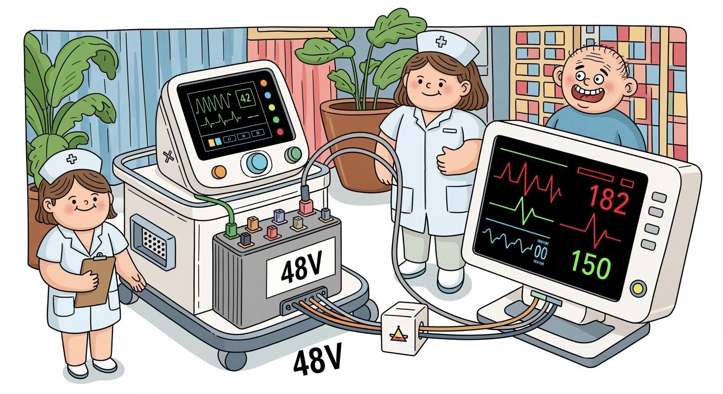
Quick Answer: A 13S NMC lithium-ion battery pack provides approximately 46.8–48.1V nominal voltage and is suitable for ventilators designed around a 48V-class DC bus. Reliable integration requires cell-level monitoring, redundant protection, temperature sensing, accurate state-of-charge estimation, and verification of backup runtime under the ventilator’s actual load profile. A 13S LiFePO4 pack provides only about 41.6V nominal voltage, so LiFePO4 systems normally require a different series configuration or power-conversion design.
When you design medical ventilator power systems, battery voltage alone does not determine reliability. The battery pack, charger, Battery Management System (BMS), power-conversion circuit, alarm logic, and ventilator controller must operate as one coordinated system.
For life-support equipment, the battery must maintain essential performance during AC power loss, peak loads, cell imbalance, temperature changes, and foreseeable faults. Protection against overcharge, over-discharge, overcurrent, short circuit, and abnormal temperature is essential, but the design must also prevent an unexpected BMS shutdown from interrupting ventilation without adequate warning or backup.
IEC 60601-1 addresses basic safety and essential performance for medical electrical equipment, while ISO 13485 provides a quality-management framework for medical-device design and manufacturing. Depending on the pack design and market, IEC 62133-2, UN 38.3, and applicable regional requirements may also need to be included in the compliance plan.
Key Takeaways
Match the battery configuration to the ventilator’s real DC input range. A 13S NMC pack is approximately 46.8–48.1V nominal, while a 13S LiFePO4 pack is approximately 41.6V nominal.
Define backup runtime using the complete ventilator load profile, including normal ventilation, startup demand, alarms, displays, communication modules, heaters, and battery aging margin.
Use a BMS and PCM design that monitors every series group, pack current, and relevant cell temperatures. Coordinate warning thresholds and shutdown behavior with the ventilator controller.
Apply risk management and verification to the complete power system. IEC 60601-1 covers basic safety and essential performance, while ISO 13485 governs quality-management processes rather than serving as a standalone battery certification.
Select chemistry according to voltage, runtime, weight, thermal behavior, cycle life, and charging requirements. NMC generally provides higher energy density, while LiFePO4 can provide longer cycle life and greater thermal stability when the system supports its voltage characteristics.
Do not apply a universal 40%–80% state-of-charge rule to ventilator backup batteries. The charging strategy must balance emergency readiness, required runtime, battery aging, and the medical device manufacturer’s validated maintenance procedure.
Validate the battery under normal operation, loss of mains power, low-battery conditions, cell imbalance, charging faults, abnormal temperature, aged-battery conditions, and applicable single-fault scenarios.
Part 1: Medical Ventilator Power Systems Requirements
1.1 Power Reliability & Backup
You must ensure that Medical Ventilator Power Systems deliver continuous power, even during outages. Hospitals use several backup solutions to protect life-support equipment.
Uninterruptible Power Supplies (UPS) provide instant power when the main supply fails.
Diesel generators start within 10 seconds, following the 10-Second Rule. These generators can run for 72 to 96 hours without needing outside fuel.
You need to size generators based on the total load of all critical devices, including ventilators.
Compliance with NFPA 99 and 110 standards is necessary for backup systems in hospitals.
Tip: Always test your backup systems regularly to confirm they meet the 10-second startup requirement.
1.2 Safety Standards & Certifications
You must follow strict safety standards when designing lithium battery packs for Medical Ventilator Power Systems. These standards protect patients and ensure reliable operation. The table below lists the main certifications you need:
Standard | Description |
|---|---|
IEC 60601 | Governs the safety and performance of electrical medical equipment. |
ISO 13485 | Ensures consistent quality management in medical battery manufacturing. |
UL 2054 | Evaluates battery safety under extreme conditions. |
UL 1642 | Specifically covers lithium-ion battery cells. |
You should always verify that your battery packs meet these certifications before deployment.
1.3 Runtime & Capacity Needs
You must calculate the runtime and capacity for your Medical Ventilator Power Systems based on real-world needs. A typical ventilator uses about 40 watts. With a well-designed battery backup, you can expect up to 24 hours of operation without draining the batteries below 50%. In emergencies, ventilators can run for an extra 10 to 12 hours.
Lithium polymer batteries are popular because they offer high energy density and low self-discharge rates.
A 3.7V, 6000mAh Li-Po cell can power a ventilator for about 8 hours.
Always include a robust Battery Management System (BMS) to protect against overcharge, over-discharge, and temperature issues.
Note: Proper sizing and regular maintenance of your battery system will maximize uptime and patient safety.
Part 2: 13S Lithium Battery Pack Fundamentals
2.1 Why 13S for 48V Systems
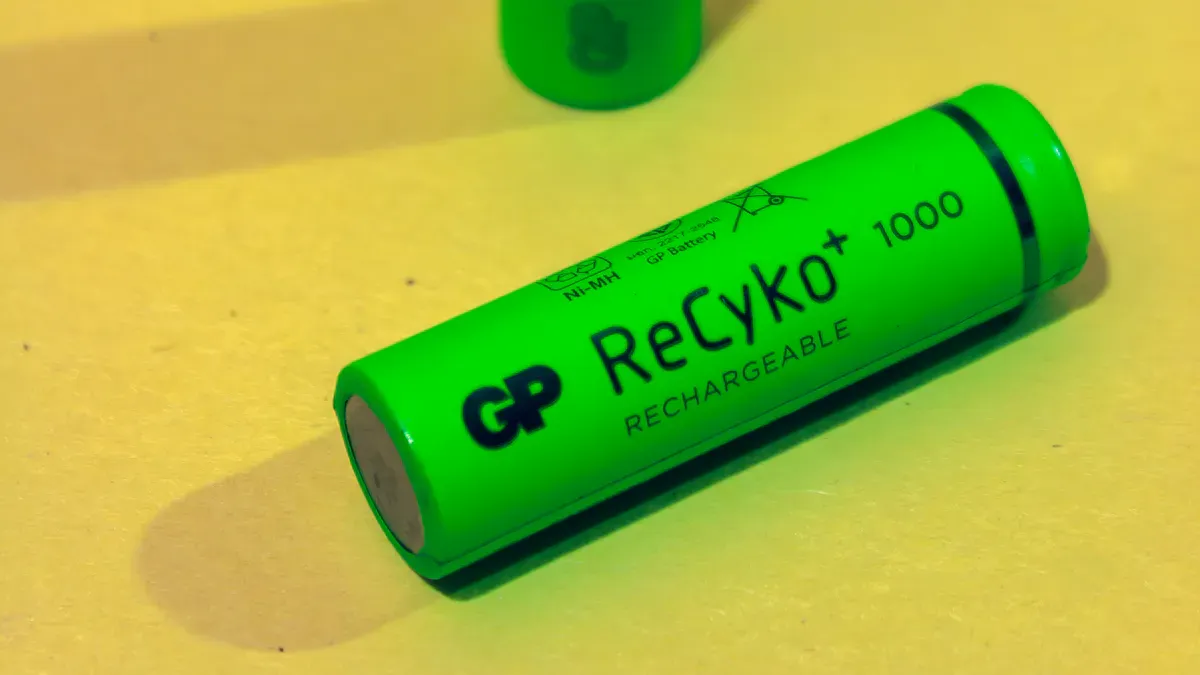
You need to select the right battery configuration for reliable power delivery. A 13S lithium battery pack connects 13 cells in series. This setup produces a nominal voltage close to 48V, which matches the requirements of many life-support devices. You see this configuration in Medical Ventilator Power Systems because it supports efficient energy transfer and reduces current losses.
A 13S arrangement gives you these advantages:
Delivers the high voltage needed for medical and industrial equipment.
Supports efficient power management, which helps maintain stable operation.
Reduces the need for heavy wiring, making the system lighter and easier to manage.
Note: Higher voltage systems like 48V allow you to use thinner wires, which reduces heat and improves safety.
2.2 Cell Chemistry & Configuration
You must choose the right cell chemistry for your application. Two common options for 13S packs are Lithium Iron Phosphate (LFP) and Lithium Nickel Manganese Cobalt Oxide (NMC). Each chemistry offers unique benefits and trade-offs. The table below compares LFP and NMC batteries for use in medical devices:
Feature | LFP Batteries | NMC Batteries |
|---|---|---|
Safety | More stable, fewer supply chain risks | Higher risk due to cobalt sourcing |
Longevity | Longer cycle life, better for longevity | Shorter cycle life |
Cost | Generally lower due to simpler materials | Higher due to cobalt and nickel costs |
Performance | Heavier, less energy density | Higher energy density, longer range |
Ethical Concerns | No cobalt usage, more sustainable | Contains 5-20% cobalt, ethical issues |
Weight | 10-15% heavier for the same capacity | Lighter for the same capacity |
Range | Shorter range, typically 15-25% less | Longer range, preferred for performance |
You also need to decide how to connect your cells. Series connections increase voltage, while parallel connections increase capacity. The table below shows how each configuration affects performance and safety:
Effect on Performance | Effect on Safety | |
|---|---|---|
Series | Increases voltage | Requires careful management to prevent overvoltage |
Parallel | Enhances capacity | Balances load across cells to prevent overheating |
The 13S configuration allows you to achieve the voltage needed for medical applications.
Parallel groups let you increase the total capacity, which extends runtime.
Proper management of both series and parallel connections protects your battery pack from failures.
Tip: Always use a high-quality Battery Management System (BMS) to monitor and balance each cell group.
2.3 Voltage, Capacity, and Cycle Life
You must understand the relationship between voltage, capacity, and cycle life to design a reliable battery pack. A 13S lithium battery pack has a nominal voltage of 48.1V (3.7V per cell × 13). The fully charged voltage reaches about 54.6V (4.2V per cell × 13). This voltage range matches the needs of most Medical Ventilator Power Systems.
Capacity depends on the number of cells connected in parallel. For example, if you use 3,000mAh cells and connect four in parallel (13S4P), you get a total capacity of 12,000mAh (12Ah). This setup provides enough energy for long runtimes, which is critical for life-support equipment.
Cycle life tells you how many charge and discharge cycles the battery can handle before its capacity drops below 80%. LFP batteries often last over 2,000 cycles, while NMC batteries usually last between 1,000 and 1,500 cycles. You should choose the chemistry that matches your needs for longevity and performance.
Callout: Always balance your need for high energy density with the safety and cycle life required in medical applications.
Part 3: BMS & Safety Integration
3.1 Modular BMS Architecture
You need a modular Battery Management System (BMS) to ensure safety and reliability in lithium battery packs for medical use. Modular BMS designs let you add or remove battery modules as your facility grows. This approach supports easy upgrades and maintenance, which is essential in dynamic hospital environments.
A modular BMS brings several safety features to your battery pack. The table below outlines the most important ones:
Feature | Description |
|---|---|
Overcharge protection | Cuts off charging at 4.25V per cell to prevent battery damage. |
Over-discharge protection | Stops discharge at 2.75V per cell to extend battery life. |
Temperature monitoring | Operates safely between -20°C and 60°C, protecting against extreme conditions. |
Short-circuit protection | Prevents hazards from accidental short circuits. |
Compliance with UL 2054 | Meets strict safety standards for battery systems. |
PTC thermistor | Suppresses thermal runaways, adding another layer of safety. |
Aluminum-laminated polymer | Prevents leaks and punctures, improving reliability. |
You can scale a modular BMS as your needs change. Hospitals often expand or renovate, so you must have a system that adapts. Modular cabling and open APIs make it easy to integrate new solutions. Centralized control simplifies daily operations and supports strategic flexibility.
Successful battery management means you can expand your system without major disruptions. You can add new assets or buildings to your BMS as your organization grows.
3.2 Smart BMS & Remote Monitoring
You should consider a smart BMS with remote monitoring for your lithium battery packs. The DALY Smart 13S BMS, for example, offers WiFi connectivity that lets you monitor battery status in real time. This feature is critical for Medical Ventilator Power Systems, where uptime and safety are non-negotiable.
A smart BMS with remote monitoring provides these benefits:
Benefit | Description |
|---|---|
Real-time monitoring | You can access live battery data and receive alerts if something goes wrong. |
Performance optimization | The system logs key data, helping you track and improve battery performance over time. |
Fault detection | The BMS records anomalies instantly, making it easier to diagnose and fix issues. |
Enhanced safety features | The BMS can shut down parts of the battery if temperatures get too high, keeping operations safe. |
Remote data transmission gives you ongoing insight into battery health.
Predictive maintenance becomes possible, reducing downtime and repair costs.
These features are especially valuable in high-demand environments like hospitals and industrial sites.
With smart BMS technology, you can respond to problems before they affect patient care or critical operations.
3.3 Redundancy & Fail-Safes
You must build redundancy and fail-safes into your BMS to protect life-support equipment. Fault-tolerant architectures prevent single points of failure. Redundant monitoring systems ensure accurate data and continuous operation, even during emergencies.
The table below lists key mechanisms for redundancy and fail-safe operation:
Mechanism | Description |
|---|---|
Fault-tolerant architectures | Prevent single points of failure, ensuring continuous operation in emergencies. |
Redundant monitoring | Use multiple monitoring systems to verify data and prevent undetected failures. |
Safety protection | Guard against overcharging, thermal runaway, and other critical failures. |
Advanced thermal management | Control battery temperature to prevent overheating and ensure safe operation. |
Sensors detect abnormal conditions early.
Isolation devices stop faults from spreading to other parts of the system.
Emergency shutdown systems activate during critical failures to protect both equipment and patients.
You should follow standards like IEC 62619 and IEC 62133. These standards set safety requirements for lithium battery packs in emergency and industrial applications.
In life-support systems, redundancy is not optional. You must design your BMS to handle faults without risking patient safety.
Part 4: Thermal & Charge Management
4.1 Temperature Sensitivity & Control
You must control temperature carefully in lithium battery packs for Medical Ventilator Power Systems. Lithium batteries work best within a specific temperature range. If you operate outside this range, you risk reduced performance or even safety hazards.
The safe operating temperature range for lithium battery packs in medical ventilators is -20°C to 60°C.
Temperatures above or below this range can cause rapid aging or failure.
To prevent overheating, you can use several thermal management solutions. The table below compares the most effective options:
Thermal Management Solution | Key Benefits |
|---|---|
Phase Change Materials (PCMs) | Absorb heat, improve temperature uniformity, passive safety, low noise |
Hybrid Cooling Systems | Combine passive and active cooling, enhance heat dissipation |
Coupled Cooling Technologies | Integrate multiple strategies for robust management under varying conditions |
Tip: Always monitor battery temperature and use the right cooling method for your application.
4.2 State-of-Charge Optimization
You can extend battery life by keeping the state-of-charge (SOC) between 40% and 80%. This practice reduces stress on battery materials and helps prevent early failure.
Keeping SOC in this range reduces exposure to extreme voltages.
High SOC (above 80%) can cause unwanted chemical reactions inside the battery.
Low SOC (below 40%) may lead to instability at the anode or copper dissolution.
Avoiding these extremes helps reduce degradation and prolongs cycle life.
The table below lists best practices for optimizing SOC in 13S lithium battery packs:
Best Practice | Description |
|---|---|
Proper Charging Settings | Set the charge controller to the correct lithium profile. |
Monitoring for Parasitic Drain | Use amp readings to find unexpected power draws. |
Importance of Cell Balancing | Regularly balance cells to maintain pack health and usable capacity. |
Note: Regular monitoring and cell balancing are key to reliable operation.
4.3 Charging Protocols & Protection
You should follow strict charging protocols to maximize safety and lifespan. Use these guidelines:
Maintain SOC between 20% and 80% to reduce stress on battery materials.
Avoid discharging below 10-15% to prevent permanent capacity loss.
Use moderate charging speeds (0.3C to 0.5C) for better battery health.
Adjust charging rates based on battery temperature.
Suspend charging if temperatures exceed 45°C.
Your charging circuit must include protection features such as:
Protection Feature | Description |
|---|---|
Over-voltage | Disconnects pack if voltage exceeds safe limits. |
Under-voltage | Disconnects pack if voltage drops too low. |
Over-current | Limits current to prevent overheating. |
Over-temperature | Disconnects pack if temperature exceeds safe range. |
Over-charge | Prevents charging beyond safe voltage. |
Over-discharge | Disconnects pack to avoid damage from low voltage. |
Short-circuit | Protects against short-circuit conditions. |
Extreme temperature | Protects from damage due to extreme temperatures. |
The Battery Management System (BMS) should also provide cell balancing, overvoltage, short circuit, undervoltage, overcharge, and overdischarge protection. These features help ensure safe and reliable operation in life-support equipment.
Part 5: Assembly, Testing & Compliance
5.1 Cell Quality & Matching
You must select high-quality cells for your lithium battery pack. Consistent cell performance ensures safety and reliability in Medical Ventilator Power Systems. You should assess each cell using strict criteria before assembly. The table below outlines the main factors you need to check:
Criteria | Description |
|---|---|
Formation & initial capacity | Measure cell capacity at the batch level to ensure consistency. |
Aging test | |
Cycle life test | Test performance over many cycles at the intended charge and discharge rates. |
Safety/abuse tests | Perform tests like nail penetration and overcharge to confirm safety. |
Supplier checks | Verify IEC 62133 certification and UN 38.3 test summary for compliance. |
Qualification tests | Run tests for capacity, internal resistance, and cycle life under specific conditions. |
Process & QC documentation | Review formation recipes, aging protocols, and selection criteria for cells. |
Warranty and failure-rate terms | Confirm warranty and failure rates for large orders. |
Tip: Always match cells by capacity and internal resistance to prevent imbalance and extend battery life.
5.2 Connectors, Wiring & Enclosure
You need to choose robust connectors and wiring for your battery pack. Use high-quality, medical-grade connectors that resist corrosion and vibration. Select wires with insulation rated for the maximum voltage and current. Secure all connections to prevent accidental disconnection during operation.
For the enclosure, pick materials that provide electrical insulation and thermal protection. The enclosure should shield the battery from dust, moisture, and impact. You should also design the enclosure for easy inspection and maintenance.
5.3 Assembly Steps & Quality Control
You must follow a clear assembly process to ensure safety and performance. Here is a typical workflow:
Inspect and sort cells by capacity and resistance.
Spot-weld or connect cells into series and parallel groups.
Attach the Battery Management System (BMS) and sensors.
Place the pack inside the enclosure and secure all components.
Test the assembled pack for voltage, capacity, and protection features.
You should document each step and use checklists for quality control. This approach helps you catch errors early and maintain high standards.
Callout: Consistent quality control reduces the risk of failure in critical medical applications.
5.4 Compliance Testing & Documentation
You must test your battery pack to meet international standards. These tests confirm safety, reliability, and legal compliance. The table below lists the main standards for lithium battery packs in medical devices:
Standard | Description |
|---|---|
IEC 62133 | Global safety standard for lithium batteries |
UN38.3 | Transport safety requirements |
IEC 60601-1 | Medical electrical equipment safety |
ISO 13485 | Quality management for medical devices |
RoHS/REACH | Environmental compliance |
You should keep detailed records of all tests and certifications. This documentation supports regulatory approval and helps you respond quickly to audits or recalls.
Note: Proper compliance testing and documentation protect your business and your patients.
Part 6: Common Pitfalls & Solutions
6.1 Overcharge/Over-Discharge Risks
You must watch for overcharge and over-discharge in lithium battery packs. These issues can damage Medical Ventilator Power Systems and put patients at risk. Overcharging often happens when the charging control system fails or the BMS does not work as designed. Sometimes, aluminum corrosion increases resistance and self-discharge, which can lead to overcharging. Contaminants like metal impurities may cause short circuits and thermal runaway during charging. Over-discharge usually results from poor energy management, a failed BMS, or using the battery beyond safe voltage limits.
Common causes of overcharge and over-discharge:
Charging continues after reaching cut-off voltage due to faulty control.
Aluminum corrosion raises resistance and self-discharge rates.
Metal impurities cause short circuits and overheating.
Improper energy management or BMS failure leads to deep discharge.
Tip: Always use a reliable BMS and test your charging systems regularly to prevent these risks.
6.2 Balancing & Monitoring Issues
Cell balancing and monitoring are critical for safe operation. If you do not balance cells, some may overcharge or over-discharge before others. This imbalance can shorten battery life and cause failures. Poor monitoring makes it hard to spot problems early. You should use a BMS with accurate cell-level monitoring and automatic balancing. Regular maintenance checks help you catch issues before they become serious.
Use a BMS that supports cell balancing.
Schedule routine inspections to verify cell voltages.
Monitor for signs of imbalance, such as uneven temperatures or rapid capacity loss.
Callout: Balanced cells and active monitoring keep your battery pack healthy and reliable.
6.3 Regulatory Challenges
Certifying lithium battery packs for medical use brings unique challenges. You cannot rely only on manufacturer specifications because real-world conditions often differ. Non-compliance with standards can delay product launches or cause rejections. Battery aging and drift over time may lead to device failure in the field. The table below summarizes key regulatory challenges and solutions:
Challenge | Risk | Mitigation / Tip |
|---|---|---|
Overreliance on battery manufacturer specs | Real use conditions differ | Test under worst-case loads |
Non-compliance with consensus standards | Regulatory delays or rejections | Use recognized standards and document conformity |
Battery aging & drift over time | Device failure in the field | Monitor battery health; design fail-safe discharge cutoffs |
Note: Always document your testing and compliance steps to support regulatory approval and ensure patient safety.
You must follow clear steps when designing a 13S lithium battery pack for 48V Medical Ventilator Power Systems. Select high-quality cells, use a smart BMS, and apply strong thermal management. Test for compliance with all safety standards. Keep monitoring and maintaining your system to ensure long-term reliability. These actions help you protect patients and support critical care.
FAQ
What makes a 13S lithium battery pack suitable for medical ventilators?
You get a stable 48V output with a 13S configuration. This matches the voltage needs of most medical ventilators. The setup supports reliable backup power and meets strict safety standards.
How does a Battery Management System (BMS) improve safety?
A BMS monitors voltage, current, and temperature for each cell. You receive alerts for abnormal conditions. The system cuts off charging or discharging if it detects unsafe values.
Which lithium battery chemistry should you choose for life-support equipment?
Chemistry Name | Cycle Life (cycles) | Energy Density (Wh/kg) | Safety Level |
|---|---|---|---|
Lithium Iron Phosphate (LFP) | 2,000+ | 90–120 | Very High |
Lithium Nickel Manganese Cobalt Oxide (NMC) | 1,000–1,500 | 150–220 | Moderate |
Choose LFP for maximum safety and long life.
How often should you test and maintain lithium battery packs?
You should test battery packs monthly. Check for voltage, capacity, and temperature issues. Schedule annual compliance tests to meet medical standards.
Can you use the same battery pack design for other sectors like robotics or security?
Yes. You can adapt the 13S lithium battery pack for robotics, security, and industrial systems. Always adjust the BMS and enclosure for each application’s safety and runtime needs.


