


Humanoid robots place unusual demands on their power systems. Joint motors may require sharp current pulses during lifting, acceleration, squatting, or balance recovery, while onboard computing and sensing create a continuous background load. In these applications, battery selection is not only an energy-density decision. Power density, voltage stability, internal resistance, thermal behavior, and pack-level consistency directly affect robot performance.
Quick Answer
Tabless cylindrical cells shorten and distribute the current path across the electrode edge instead of concentrating current through one or several conventional tabs. This architecture can reduce internal resistance, improve current distribution, and limit localized heating during high-power operation. For humanoid robots, these advantages may support stronger peak-power response and more manageable pack temperatures. However, tabless construction does not automatically guarantee fast charging, long cycle life, or a reliable robot battery. Cell quality, pack interconnections, thermal management, BMS calibration, and charger coordination remain decisive.
Key Takeaways
- Humanoid robot batteries must be evaluated for sustained power and transient voltage response, not energy density alone.
- Tabless cells distribute current collection across a wider electrode edge, helping reduce resistance and localized heat.
- Lower cell resistance can improve high-current performance, but pack busbars, welds, connectors, and wiring may become the next bottlenecks.
- A high discharge-rate rating does not automatically indicate safe fast-charging capability.
- Cell consistency, cooling, protection logic, and communication with the charger determine pack-level reliability.
- Robot manufacturers should validate performance using realistic motion profiles rather than relying only on short pulse-current specifications.
Part 1: Why Humanoid Robots Have a Power-Density Problem
1.1 Dynamic Motion Creates Short, High-Current Loads
A robot rarely consumes power at a constant rate. Walking, standing, lifting, sudden acceleration, joint locking, and recovery from external disturbance can produce very different electrical loads. A battery may supply moderate current during normal movement and then face a much higher pulse when several joint motors act at the same time.
This means a cell that looks adequate from an amp-hour calculation may still produce excessive voltage sag or heat during dynamic operation. Engineers should evaluate:
- Continuous discharge current
- Peak current magnitude and duration
- Voltage sag during repeated pulses
- Temperature rise over a complete duty cycle
- Power capability at low state of charge
- Performance after hundreds of cycles
1.2 Energy Density Is Important, but It Is Not the Only Priority
Higher energy density can extend runtime or reduce pack weight, but a robot also needs sufficient power density to convert stored energy into useful mechanical output. A lightweight, high-energy cell may not be suitable if its internal resistance causes excessive voltage drop during peak loads.
The engineering objective is therefore to balance runtime, mass, volume, output power, cooling requirements, and service life. Large Power develops custom robot battery solutions around the actual motor load, control architecture, installation space, and operating environment.
Part 2: What Is a Tabless Battery Cell?
2.1 Tabless vs Full-Tab Terminology
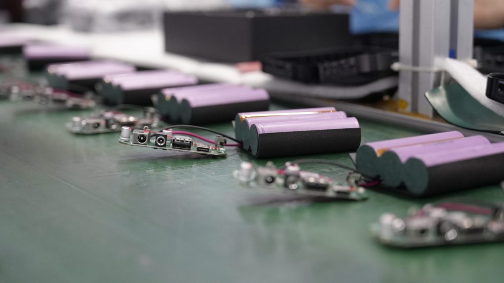
The industry commonly uses the term tabless cell, although the electrode still requires an electrical connection to the terminal. The term generally describes a design in which a large portion of the electrode edge acts as a continuous or distributed current-collection interface. It may also be described as a full-tab, continuous-tab, or shingled-tab architecture depending on the manufacturer and production method.
A conventional cylindrical cell collects current through one or several discrete tabs. Current must travel laterally through the foil before reaching those connection points. In a tabless design, the effective current path is shorter and distributed over a wider area.
2.2 Why the Current Path Matters
Electrical resistance converts part of the battery’s output into heat according to P = I²R. Because heating rises with the square of current, even a modest resistance reduction can become valuable during high-current robot movements.
| Design Consideration | Conventional Tab Structure | Tabless Structure |
|---|---|---|
| Current collection | Concentrated at discrete tabs | Distributed along a wider electrode edge |
| Effective current path | Longer through portions of the foil | Generally shorter and more uniform |
| Localized heating | More likely near tab regions | Potentially reduced through distributed collection |
| High-current response | Depends strongly on tab count and placement | Can support lower resistance and improved power delivery |
| Manufacturing | Mature and widely standardized | More demanding edge forming, alignment, and welding |
Part 3: Advantages for Humanoid Robot Battery Packs
3.1 Lower Internal Resistance and Reduced Voltage Sag
When several actuators demand power simultaneously, lower cell resistance can help the pack maintain a more stable voltage. This supports motor controllers, computing hardware, and safety electronics that may react poorly to a sharp voltage drop.
The benefit should be verified at pack level. Nickel strips, copper busbars, welds, fuses, connectors, cables, and contactors all add resistance. Once cell resistance is reduced, these components may account for a larger share of total loss.
3.2 More Uniform Heat Distribution
Distributed current collection can reduce concentrated heating around individual tabs. More uniform cell temperature may simplify pack cooling and reduce temperature differences between cells. This is important because uneven temperature accelerates uneven aging, which can increase imbalance and reduce usable pack capacity.
Tabless architecture does not eliminate heat. High-current operation still produces electrochemical and resistive losses. Engineers must provide suitable thermal paths, sensor placement, spacing, enclosure ventilation, and operating limits.
3.3 Better Support for Repeated High-Power Events
A humanoid robot may repeat the same demanding motion many times during a shift. A useful high-power cell must therefore handle repeated pulses without excessive cumulative heating. Testing should reproduce the robot’s real motion cycle rather than applying only one short laboratory pulse.
Recommended measurements include minimum pack voltage, maximum cell temperature, temperature spread, current-path temperature at welds and connectors, and recovery time between power events.
Part 4: Engineering Trade-Offs and Manufacturing Limits
4.1 Tabless Cells Are More Difficult to Manufacture
The distributed electrode edge must be formed, aligned, and connected consistently. Variations in edge geometry or weld quality can create uneven current distribution, increased resistance, or mechanical weakness. Production yield and quality-control requirements may therefore be more demanding than for established conventional-tab cells.
4.2 Cell-Level Performance Does Not Guarantee Pack-Level Performance
A low-resistance cell can still underperform in a pack with poorly designed interconnections or inconsistent cooling. Pack engineers should evaluate:
- Cell-to-cell direct-current resistance distribution
- Weld resistance and mechanical strength
- Busbar material and cross-sectional area
- Fuse and contactor resistance
- Connector temperature under sustained current
- Sensor location and thermal response time
- Parallel-group current sharing
4.3 Capacity, Power, and Cycle Life Must Be Balanced
Optimizing an electrode for high power can affect energy density, cycle life, or cost. The best cell is not necessarily the one with the highest advertised discharge rate. Robot manufacturers should compare sustained performance, thermal rise, aging behavior, sourcing stability, and pack integration requirements.
Part 5: Tabless Cells Are Only One Part of the Robot Energy System
Tabless cells can reduce current-path resistance and improve heat distribution during high-power discharge, but cell structure alone does not determine robot uptime. A practical robot energy system must coordinate the cells, battery pack, Battery Management System (BMS), charger, and robot controller.
After high-load movements such as lifting, jumping, or rapid acceleration, the battery may enter the charging station with elevated temperature, low state of charge, or increasing cell-to-cell imbalance. Applying the same fixed charging current under every condition can accelerate degradation or push individual cells closer to their voltage and temperature limits.
A smart charging process should follow this sequence:
Battery identification → status acquisition → safety check → charging strategy selection → dynamic current control → continuous monitoring → charge completion
Through CAN or RS-485 communication, the charger can receive pack voltage, cell voltage, temperature, state of charge, and fault information from the BMS. Charging current can then be reduced or suspended when the battery approaches its thermal or voltage limits.
5.1 Why Tabless Does Not Automatically Mean Fast Charging
Lower internal resistance can help a tabless cell manage higher current with less resistive heating. However, this does not automatically qualify the cell or battery pack for fast charging. Charging performance also depends on:
- Cell chemistry and electrode design
- Anode lithium-plating limits
- Cell temperature and thermal uniformity
- Pack-level interconnection resistance
- Cell matching and balancing accuracy
- BMS protection thresholds
- Charger communication and control logic
For humanoid robots, charging speed should be defined by validated current, voltage, temperature, and cycle-life boundaries rather than by the cell’s peak discharge rating.
5.2 From Manual Charging to Autonomous Recharging
As robots move into factories, warehouses, inspection sites, and service environments, autonomous recharging will become part of the operating system rather than a separate accessory. A mature workflow may include:
Low-energy detection → return to charging station → pack identification → safety validation → controlled charging → completion confirmation → return to operation
This makes energy-system integration especially important. A custom robot battery should consider the tabless cell, pack architecture, thermal management, BMS communication, charging interface, and duty cycle together. For fleet operators, the final objective is not simply the shortest charging time. It is higher robot availability with controlled temperature, predictable battery life, and less manual intervention.
Part 6: How to Evaluate Tabless Cells for a Robot Project
6.1 Test Sustained Current, Not Only Peak Current
A brief pulse rating may not represent a robot’s repeated high-load operation. Request voltage and temperature curves for a realistic sustained-current period and for repeated pulse cycles. Confirm the starting state of charge and ambient temperature for every comparison.
6.2 Compare Resistance and Consistency Within the Same Batch
Average resistance is not enough. The spread between cells affects parallel current sharing and pack aging. Define incoming inspection limits for capacity, open-circuit voltage, direct-current resistance, dimensions, weight, and traceability.
6.3 Measure Performance After Aging
A new cell may deliver excellent power, but robot platforms require predictable performance over time. Evaluate capacity retention, resistance growth, voltage sag, and temperature rise after representative cycling. End-of-life criteria should include power capability as well as remaining capacity.
6.4 Validate Low-Temperature Performance
Robots that move between indoor and outdoor environments may experience large temperature changes. Cold conditions increase cell resistance and reduce available power. Charging below the permitted temperature may also create lithium-plating risk. A low-temperature battery solution, pack heater, or charging lockout may be required.
6.5 Review Safety, Certification, and Traceability
The final battery pack should be evaluated against the standards and transport requirements applicable to its market and use. Important considerations may include UN 38.3, IEC 62133-2, IEC 62619, functional safety requirements, enclosure protection, and documented change control. The applicable standard depends on the final robot, battery architecture, and target market.
Part 7: Choosing Between Cylindrical, Pouch, and Prismatic Cells
| Cell Format | Typical Strength | Engineering Consideration | Potential Robot Application |
|---|---|---|---|
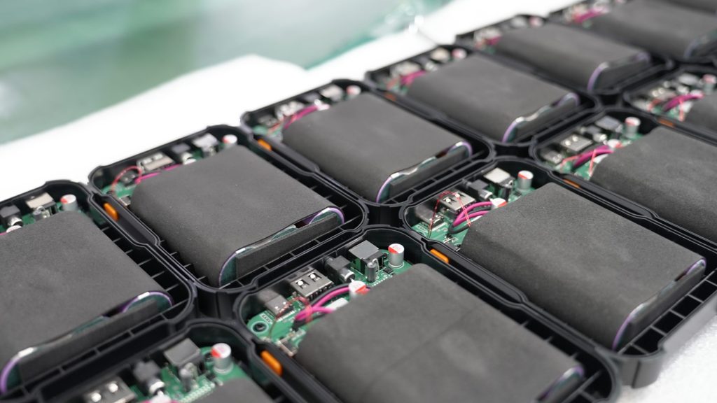
| Cylindrical cells | Mature supply chain, mechanical consistency, distributed pack layout | Lower volumetric packing efficiency and many interconnections | High-dynamic humanoid and mobile robots |
| Pouch cells | Lightweight, thin, flexible dimensions | Requires compression control and swelling allowance | Space-constrained or lightweight platforms |
| Prismatic cells | High pack-level space utilization and fewer interconnections | Thermal gradients and mechanical restraint require attention | Larger mobile robots and stationary robotic systems |
Tabless construction is most visible in cylindrical-cell development, but format selection should follow the robot’s mechanical envelope, power profile, cooling method, maintenance strategy, and expected production volume.
Conclusion
Tabless battery cells offer a meaningful structural approach to the power and thermal challenges of humanoid robots. By distributing current collection across the electrode edge, they can reduce resistance, limit localized heating, and improve high-current response. Their value is strongest in applications with repeated dynamic loads and tight thermal constraints.
They are not a universal solution. Manufacturing consistency, cell aging, pack interconnections, BMS logic, cooling, and charging strategy determine whether cell-level advantages become reliable robot performance. The right development process begins with the robot’s duty cycle and validates the complete energy system under realistic conditions.
For voltage, capacity, discharge-current, communication, thermal-management, and enclosure integration support, discuss your requirements with Large Power through our custom battery consultation.
FAQ
What is a tabless battery cell?
A tabless cell uses a distributed current-collection connection along a larger portion of the electrode edge instead of relying only on one or several conventional tabs. The shorter, wider current path can reduce resistance and improve heat distribution.
Why are tabless cells suitable for humanoid robots?
Humanoid robots create repeated high-current loads during dynamic movement. Lower resistance and more uniform current collection can reduce voltage sag and localized heating, supporting more stable power delivery.
Does a tabless cell support fast charging?
Not automatically. Fast-charging capability depends on chemistry, electrode design, anode behavior, temperature, state of charge, BMS limits, and charger control. A high discharge rating should not be treated as proof of an equally high charge rate.
Are tabless and full-tab cells the same?
The terms are often used for closely related distributed current-collection structures. “Tabless” is the more common market term, while full-tab, continuous-tab, and shingled-tab may describe specific implementations. Engineers should review the manufacturer’s actual construction and test data.
What should robot manufacturers test before selecting a tabless cell?
Test sustained and repeated pulse current, voltage sag, temperature rise, resistance distribution, low-temperature behavior, aging performance, cell consistency, and pack-level interconnection losses. Validation should reproduce the robot’s real operating cycle.


