

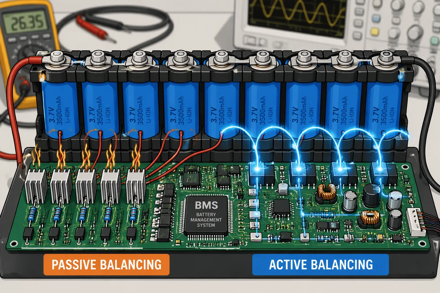
Choosing passive or active cell balancing for a large series battery pack starts with the imbalance that must be corrected, not a fixed series-count threshold. Cell capacity, self-discharge, available balancing time, thermal limits and energy-transfer paths determine whether a simple bleed circuit is sufficient or active redistribution adds practical value.
For industrial, robotics and infrastructure equipment, the objective is to maintain usable pack capacity within cell operating limits. Neither method repairs degraded cells, replaces protection circuitry or guarantees a longer service life.
Quick Answer
Use passive balancing when the required charge correction fits the available balancing window and resistor heat is manageable. Evaluate active balancing when greater charge transfer or energy recovery is needed, especially with large-capacity cells or limited charging opportunities. There is no universal 14-series crossover: size the balancing current from the estimated charge mismatch and validate the complete BMS.
Key Takeaways
Estimate imbalance in ampere-hours; voltage difference alone cannot establish balancing time.
Passive balancing dissipates removed energy. Active balancing transfers energy with conversion and standby losses.
Series count affects architecture and scheduling, but cell capacity and duty cycle often drive current requirements.
LiFePO4’s flat voltage curve requires careful voltage-based balancing decisions.
Keep cell protection independent of the balancing strategy and validate fault behavior.
Part 1: Understand the Imbalance Before Selecting Hardware
1.1 SOC, Capacity and Resistance Are Different Problems
Cells can differ in state of charge, available capacity, resistance and self-discharge. SOC imbalance means their charge states are misaligned. Capacity mismatch means one cell stores less usable charge even when all cells are correctly aligned. Balancing can redistribute or remove charge, but it cannot restore lost capacity or eliminate a damaged connection.
In a series string, the same string current passes through every series group. A high-resistance weld creates a voltage drop and heating; it does not make neighboring cells carry extra series current. Diagnose interconnect faults rather than trying to balance away their symptoms.
Cell sorting, traceability, appropriate interconnect design and uniform cooling reduce the burden placed on the balancer. Persistent drift or unusually frequent balancing should trigger investigation of self-discharge, measurement errors, temperature gradients or cell deterioration.
1.2 Interpret Voltage in Its Operating Context
Terminal voltage depends on SOC, current, temperature, polarization and cell resistance. A 90 mV spread under load is not equivalent to a specified charge mismatch. Compare readings under defined conditions and use a cell model or characterized charge curve where appropriate.
For LiFePO4, a small voltage change across much of the SOC range can correspond to a substantial SOC difference. Conversely, transient voltage divergence may not represent a lasting imbalance. Top-of-charge balancing can be practical, but its enable voltage, current limits and hysteresis must follow the selected cell and charging strategy. A universal 3.5 V trigger is unsuitable for every chemistry.
1.3 Keep Protection Separate from Balancing
An imbalanced string may reach an individual cell limit before reaching the expected pack capacity. The charger and battery management system must reduce or stop current as required. Overcharge and over-discharge are not inevitable consequences of imbalance in a correctly protected system.
Balancing is a capacity-management function, not permission to exceed cell voltage or temperature limits. If a balancing channel fails, independent protection must still enforce the required safe operating conditions.
Part 2: Passive Balancing and Its Thermal Budget
2.1 How a Bleed Circuit Works
A passive balancer switches a resistor across a selected cell or series group. It removes charge from that group as heat, often during a suitable charging or rest window. The control algorithm defines which channels run, when voltage is sampled and which temperature or fault conditions inhibit balancing.
There is no universal 0.25 A maximum. For example, TI’s BQ79616 datasheet describes passive balancing whose current depends on cell voltage, the external resistor and switch resistance. The implemented current must remain within component and thermal limits; a component example is not a specification for all passive BMS designs.
2.2 Calculate Heat and Available Correction
For an approximate resistive channel, balancing current is I = V/R and resistor power is P = V × I. Use the actual voltage range, switch losses, resistor tolerance and duty cycle in the detailed calculation.
At 4.0 V and 0.10 A, one channel dissipates approximately 0.40 W. Ten simultaneously enabled channels dissipate about 4 W in their bleed paths before other electronics losses. This illustrative case shows why channel scheduling and enclosure temperature matter.
Check resistor derating, PCB hot spots, nearby cell temperatures and the number of channels permitted to operate together. Voltage-sampling restrictions and thermal pauses reduce effective balancing current. Passive balancing may operate during permitted normal use or charging; it does not inherently require the entire pack to remain unavailable.
Part 3: Active Balancing and Energy-Transfer Paths
3.1 Topology Determines What Can Be Corrected
Active circuits transfer energy through capacitors, inductors or transformers. Depending on topology, they may transfer between adjacent cells, between a cell and a group, or between a cell and the pack. These paths determine transfer distance, channel concurrency and control requirements.
Adjacent-cell transfer may need multiple stages to move energy across a long string. Shared converters may service only one or a limited number of channels at a time. A high advertised channel current therefore does not establish the equalization time for the complete pack.
Analog Devices’ LTC3300-1 datasheet gives an example of transformer-based bidirectional active balancing with current set by external components and support for up to 10 A. This demonstrates that 6 A is not a universal ceiling. Actual performance depends on magnetics, switches, cooling, cell voltages and operating conditions.
3.2 Include Conversion Losses and Standby Consumption
Active balancing is not lossless. Measure transferred energy at defined source and destination boundaries. Efficiency varies with transfer power, voltage ratio, topology and loading; a single headline percentage should not be applied across all operating states.
If 10 Wh is drawn from a donor and 9 Wh reaches the receiving side, transfer efficiency is 90% and the transfer loss is 1 Wh. Account for auxiliary and standby energy separately if excluded from those measurements. For passive balancing, removed charge is dissipated rather than recovered in another cell; describing this as 70–80% redistribution efficiency is misleading.
At high transfer currents, active circuitry can still create significant local heat. Verify converter losses and cell heating rather than assuming that active hardware always runs cooler. Quiescent current is product-specific, not a universal 50 mW overhead.
Part 4: Compare Strategies Using a Charge Budget

4.1 Estimate Time from Ampere-Hours
A first-order estimate is t = ΔQ / Ieffective, where ΔQ is the charge correction in Ah and Ieffective is the average correction current at the relevant cell boundary. Include duty cycle, thermal pauses, channel sharing and transfer direction. For active systems, input current and delivered receiver current need not be equal.
Consider a 100 Ah series group with an estimated 1% SOC offset, corresponding approximately to 1 Ah. At 0.10 A effective correction, the idealized time is 10 hours. At 1.0 A, it is 1 hour. These are illustrative lower-complexity estimates, not guarantees for a complete pack.
For a 5 Ah group with the same percentage offset, the correction is only 0.05 Ah: about 30 minutes at 0.10 A under the same assumptions. Cell capacity therefore matters greatly. Multiply time by series count only when the actual hardware schedules those corrections sequentially; simultaneous channels behave differently.
4.2 Define a Fair Comparison
Criterion | Passive Balancing | Active Balancing |
|---|---|---|
Energy destination | Removed energy becomes heat | Part is recovered at another cell or group |
Current capability | Set by channel components and cooling | Set by converter and transfer topology |
Time to correct | Charge mismatch divided by effective bleed current | Effective transfer plus routing and scheduling |
Implementation | Usually fewer components and simpler control | Additional switching, storage elements and diagnostics |
Large series strings | Viable if charge and thermal budgets fit | Useful where transfer benefits justify added complexity |
Compare usable capacity, charging duration, heat, sleep consumption, BOM cost and service requirements over representative operating cycles. No fixed percentage improvement in lifespan or total cost follows solely from the selected topology.
Part 5: Selection and Validation for Large Series Packs
5.1 Start with the Requirements
Specify series and parallel configuration, group capacity, chemistry, expected drift, charging profile and the available balancing window. Include module-to-module differences: a system that balances within modules may not correct imbalance between modules.
Passive balancing is a reasonable candidate when expected drift is small and there is enough time to correct it within the heat budget, including in high-cycle or high-series-count systems. Active balancing deserves evaluation when passive correction is insufficient or recovered energy has measurable operational value. A long cycle-life target alone does not mandate active balancing.
Safety requirements depend on the equipment and its risk analysis. Neither automotive nor industrial functional-safety frameworks create a universal requirement to use active balancing. Both approaches need suitable diagnostics and fault containment for the allocated safety functions.
5.2 Test Normal Operation and Faults
Inject known charge offsets and verify convergence across operating temperatures and SOC ranges.
Measure channel current, total heat and correction time with the actual enclosure and scheduling.
Check voltage accuracy while balancing and after the specified settling interval.
Test stuck-on or open channels, sense-wire faults, communication loss and controller resets.
For active hardware, assess unintended transfers, converter faults and relevant isolation boundaries.
Verify sleep current, storage behavior and repeated operation with aged cells.
A balancer that appears effective on fresh matched cells may behave differently after uneven aging. Track persistent correction demand and service thresholds. Cells with abnormal leakage or deteriorated capacity need diagnosis and possible replacement, not unlimited balancing.
When developing custom lithium battery packs, agree on measurable balancing requirements early. Combine BMS hardware selection with a verification and testing plan that covers electrical, thermal and fault behavior.
FAQ
Does a Pack Above 14S Require Active Balancing?
No. Series count affects architecture, but there is no universal 14S cutoff. Calculate required correction current from group capacity, expected mismatch, balancing time and thermal constraints.
Can a Voltage Difference Predict Balancing Time?
Not by itself. Voltage also depends on load, temperature and resistance. Estimate the charge mismatch using characterized cell behavior and then account for effective current and channel scheduling.
Can Passive Balancing Support Long-Life LiFePO4 Packs?
Yes, if it corrects the expected imbalance within the available window. Set chemistry-specific enable conditions and consider the flat voltage curve. Validate aged-cell behavior as well as fresh-cell results.
Does Active Balancing Restore a Weak Cell?
No. It can improve use of charge within the string, but it cannot restore lost capacity, fix an internal defect or repair a poor connection. Persistent imbalance warrants investigation.
Is Balancing a Substitute for Overvoltage Protection?
No. Protection must enforce individual cell limits independently. Charging may need to be reduced or stopped even when balancing is active.


