


Battery pack end-of-line testing verifies that an assembled unit meets its approved production release requirements. For OEMs, a useful EOL plan connects electrical measurements, BMS checks, assembly records and shipment preparation to the pack’s serial number and controlled design revision.
EOL testing is not a substitute for design qualification, incoming cell inspection or process control. A short final test cannot prove long-term cycle life or detect every latent defect. Its value comes from validated coverage of manufacturing faults and clear release criteria, not an unsupported claim that it catches 98% of failures.
Quick Answer
Before shipment, verify pack identity and configuration, polarity and voltage, controlled-load response, BMS measurements and communication, protection functions using approved test methods, assembly and sealing records, and transport readiness. Separate checks required on every unit from sampling and type tests. Record limits, measured values and disposition, and prevent failed or incomplete units from being released.
Key Takeaways
Define the EOL plan from the pack design, manufacturing risks and customer requirements.
Use safe stimulation or simulation for protection checks; do not deliberately abuse shipment units.
Keep capacity characterization, environmental qualification and UN 38.3 design tests separate from routine EOL screening.
Validate test fixtures, measurement uncertainty and software-controlled acceptance limits.
Apply shipping SOC and labeling rules to the actual transport mode and packing instruction.
Part 1: Electrical and BMS Verification
1.1 Identity, Polarity and Voltage
Read the serial number and confirm the cell model, series/parallel configuration, pack part number and hardware revision against the manufacturing record. Check connector pinout, output polarity, pack voltage and individual series-group voltages where accessible through approved interfaces.
Measure voltage spread under specified temperature, rest time and SOC conditions. A universal millivolt limit is inappropriate across all chemistries and states. Compare the reference measurements with BMS readings and investigate missing channels, inconsistent values or open-wire diagnostics.
Do not infer full capacity, electrode quality or lifetime from open-circuit voltage alone. Cell capacity sorting is normally an upstream activity; EOL should verify that the approved cell lots and grouping records were used.
1.2 Load Response and Resistance Measurements
A controlled load pulse can screen for abnormal voltage drop, connection resistance and output-switch behavior. Define the pulse amplitude, duration, SOC, temperature and allowable recovery before using it as a release test.
A DC resistance estimate uses the voltage change divided by the current change at a specified measurement time. Its result includes the behavior of cells, interconnects, protection switches and the test fixture. AC impedance is a different measurement and is not interchangeable with DC pulse resistance.
Fixture contacts can dominate small resistance readings. Use suitable sensing arrangements, monitor fixture wear and validate repeatability. A relative deviation calculated as (measured resistance minus reference resistance) / reference resistance × 100 is a percentage, not a value in milliohms.
1.3 BMS Configuration, Communication and Measurements
Verify the approved firmware, parameter set, cell count, current calibration, temperature channels and protection settings. For smart packs, exercise the implemented interface, such as SMBus, CAN or RS485, including identifiers, message scaling, units and timeout behavior.
Compare reported voltage, current and temperature against calibrated references. Check charge enable, discharge enable, wake-up, sleep and recovery states where applicable. A missing or implausible temperature reading must not silently pass as a normal measurement.
The BMS and protection architecture determines which tests are meaningful. A small MOSFET-switched pack and a contactor-based HV pack should not share an unmodified checklist.
1.4 Protection Checks Without Damaging the Pack
Use approved simulation, service interfaces or controlled stimuli to verify fault recognition and the intended protective response. Assess overvoltage, undervoltage, overcurrent, temperature and communication faults according to the design. Confirm recovery behavior as well as fault entry.
Do not overcharge real cells, apply uncontrolled short circuits or heat shipment units beyond permitted limits to demonstrate protection. More severe fault tests belong in qualification using designated samples and suitable safety facilities.
For HV packs, include contactor feedback, pre-charge response, interlock continuity and relevant insulation checks. Insulation resistance and dielectric withstand are different tests. Their voltage, duration, connections and limits must come from the applicable product requirements and approved procedure; IEC 62133-2 is not a universal HV-pack EOL test prescription. Protect sensitive electronics from unsuitable test voltages.
Part 2: Mechanical Integrity and Traceable Release

2.1 Assembly Records and Inspection
Verify routing, insulation placement, connectors, labels, fasteners and visible damage against approved workmanship criteria. Link cell lots, welding process records and fastening results to the pack identifier. Final electrical testing does not replace weld process qualification or in-process inspection.
Where torque is controlled during assembly, retain the validated tool result rather than repeatedly tightening completed joints as an informal final check. Additional torque inspection must use a defined method that does not disturb the joint.
Traceability supports investigation and containment, but it does not guarantee a specific return rate, first-pass yield or OEE. Establish those metrics from the manufacturer’s own data and agreed definitions.
2.2 Leak Testing Is Not an IP Certification
For sealed designs, a validated pressure-decay, flow or tracer-gas test can screen assembly leaks. Define test pressure, stabilization time, leakage limit, temperature effects and fixture performance. Avoid pressure levels that damage seals or interfere with safety vents.
A production leak-test result does not by itself establish an IP rating. Correlate the screening method with the required ingress qualification, including relevant interfaces and vent structures.
Vibration, shock, thermal cycling and ingress qualification usually use specified samples rather than every shipment unit. Apply routine or sampled mechanical tests only where justified by the production control plan. Passing a transport vibration test does not guarantee years of service in a robot.
2.3 Control Test Data and Failed Units
Record the unit identifier, test date, station and fixture identifiers, instrument calibration status, software revision, acceptance-limit revision, actual measurements and pass/fail result. Capture deviations and approved rework, not just the final green indicator.
Use reference units and known-fault challenges to check station performance. Validate repeatability, uncertainty and decision margins near limits. Lock release when a required test is missing or the station is out of control.
Quarantine failed units, investigate the cause and define the tests required after repair. Repeatedly retesting until a unit happens to pass is not an acceptable disposition method.
Part 3: Shipment Readiness and Transport Requirements
3.1 UN 38.3 Evidence Is a Design-Level Check
The PHMSA explanation of lithium battery test summaries distinguishes design testing from shipment documentation. Confirm that the cell and battery types have the applicable UN 38.3 evidence and that the supplied pack matches the covered design. Make the required test summary available.
Do not repeat the complete T1–T8 series on each saleable pack. Test applicability and acceptance criteria differ by test and by cell or battery type. A blanket rule that every sample must retain 90% voltage and show no venting in every test misrepresents the test series.
Review design changes for their effect on the existing evidence. A cell substitution, protection change or assembly modification may require reassessment; a cell test report alone does not automatically cover every finished pack built from it.
3.2 Classification, Packaging and Labels
Identify whether batteries ship on their own, packed with equipment or contained in equipment, and determine the applicable classification and packing instruction. Verify terminal protection, movement restraint, packaging, marks, labels and documents for the actual shipment. Carrier and route restrictions also matter.
Use IATA’s official battery guidance for air-transport planning and confirm the current provisions with the responsible dangerous-goods shipping team. Battery size alone is not sufficient to decide labeling or packaging requirements.
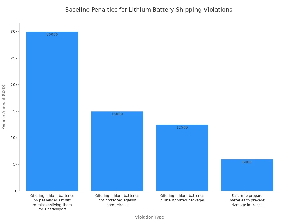
Do not treat historic penalty figures as universal current amounts. Enforcement depends on jurisdiction, violation and the applicable rules. The retained chart below is historical illustrative material, not a current penalty schedule; verify any legal amount before relying on it.
3.3 Apply SOC Limits to the Actual Shipping Category
The 30% SOC limit is not a blanket rule for all lithium battery shipments by road, sea and air. For air cargo, UN 3480 lithium-ion batteries under PI 965 have a 30% limit subject to applicable approval provisions. In 2026, PI 966 batteries packed with equipment also have a 30% requirement where the cell or battery exceeds 2.7 Wh, subject to the relevant provisions.
Do not automatically apply PI 966 conditions to batteries contained in equipment under PI 967. Check the actual packing instruction, regulatory edition and operator requirements. Do not treat a 25% displayed-capacity reading as a universal substitute for measured SOC across shipment categories.
Define an approved conditioning process and leave allowance for SOC estimation uncertainty. Record the target, method, temperature, time and final result. Terminal voltage alone is a poor SOC proxy for some chemistries, especially LiFePO4 across its flat voltage region.
Part 4: An OEM Release Checklist
Release Area | Evidence to Review |
|---|---|
Identity and configuration | Part number, serial number, cell lots, firmware and approved parameters |
Electrical screening | Polarity, voltage channels, controlled-load response and applicable insulation checks |
BMS and protection | Reference comparisons, communication, simulated faults and recovery behavior |
Assembly integrity | Workmanship, process records and validated leak screening where required |
Release disposition | Complete results, limit revisions, rework records and approval |
Shipment readiness | Applicable test summary, classification, packaging, SOC and documents |
Set test cycle time from the necessary coverage and production architecture. There is no universal 10–20-minute requirement. Full capacity measurement can take much longer than a short functional screen, so define whether it belongs on every unit, a sampled audit or upstream qualification.
Automation can improve consistency and data capture, but it does not compensate for an inadequate test plan. Validate the fault coverage and release logic before scaling line throughput.
For custom battery projects, agree on the release specification and customer acceptance evidence before production. Connect it to the broader testing and certification plan, with clear boundaries between qualification, manufacturing screening and shipment preparation.
FAQ
Must Every Pack Undergo Full Capacity Cycling at EOL?
Not universally. Determine the requirement from the product specification and control plan. A short load test does not prove capacity; any claim based on sampled testing must be supported by the approved process and evidence.
Should UN 38.3 Tests Be Repeated on Each Shipment Unit?
No. They are design-type tests with defined applicability. Verify design coverage and documentation, then perform the routine production checks established for each unit.
Can a Leak Test Confirm IP67?
Not on its own. A production leak screen must be correlated with the applicable ingress qualification. Seals, vents, connectors and the complete enclosure affect the result.
How Should Protection Functions Be Tested Safely?
Use validated simulation or controlled stimuli and check both the protective response and recovery. Avoid damaging cells or exposing production units to uncontrolled abuse.
Must All Batteries Ship Below 30% SOC?
No. The requirement depends on transport mode, classification and packing instruction. Check the current rules for the actual shipment and document the approved SOC verification method.


