

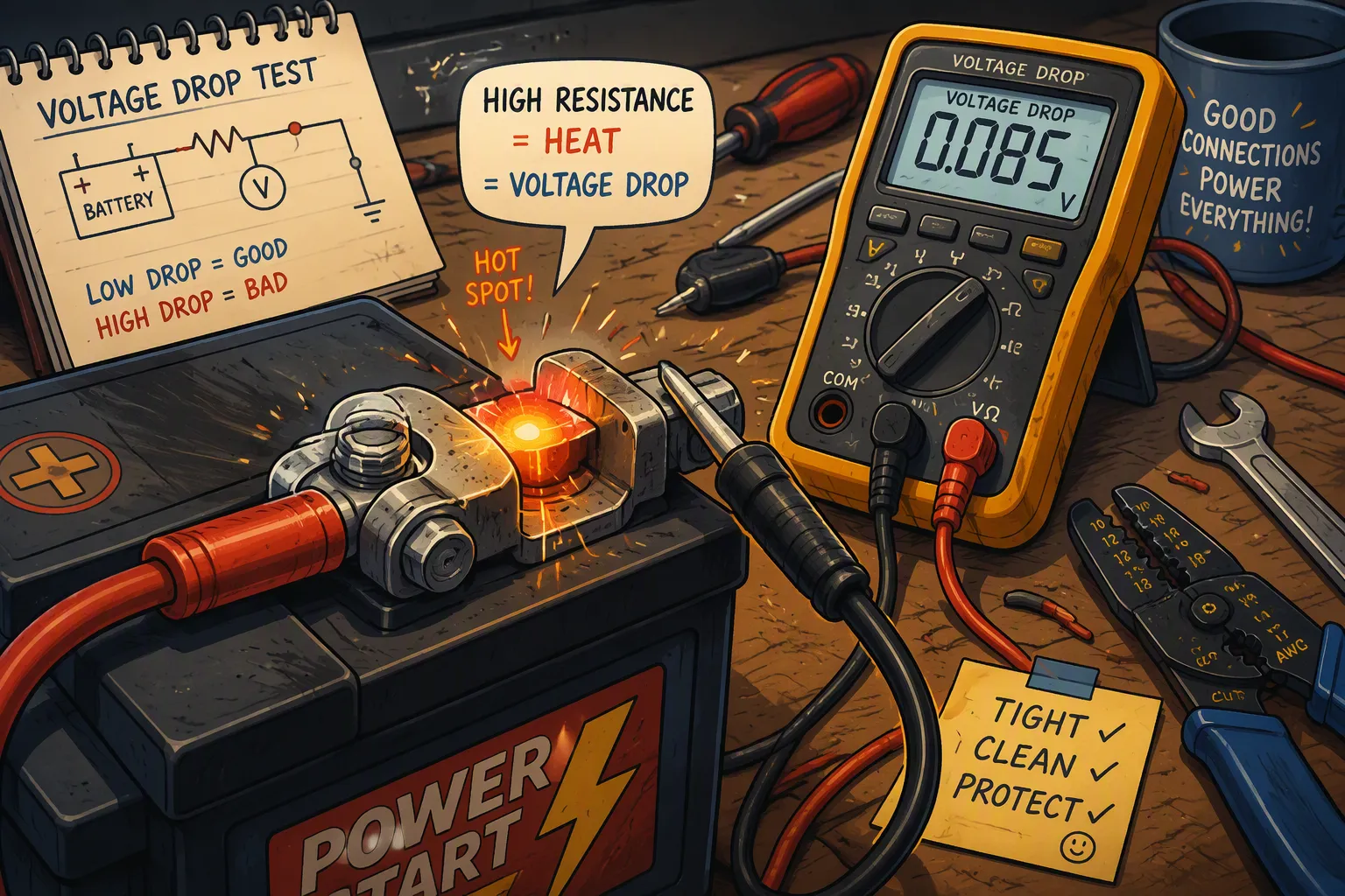
A lithium battery pack can pass a capacity test yet still produce excessive voltage drop or a hot connection in the device. The problem may be in a mating contact, crimp termination, adapter, or bolted joint rather than inside the cells. At high current, a small resistance increase can become a significant local heat source.
Battery connector contact resistance therefore belongs in the design and validation plan for custom lithium battery packs. The objective is to establish a low, stable power-path resistance throughout the intended load profile, environment and mating life.
Quick Answer: Calculate voltage loss with Vdrop = I × R and local heating with P = I² × R. Define exactly which interface or assembly the resistance represents, then measure it using a suitable four-wire method and verify temperature rise under representative load. Select acceptance limits from the connector specification and the device’s voltage and thermal budgets, including aging and environmental exposure.
Key Takeaways
Contact resistance is one part of total power-path resistance, not the same as cell internal resistance.
Current has a squared effect on resistive heating.
A connection can overheat below the BMS overcurrent threshold.
Use connector-specific measurement conditions and acceptance limits.
Verify performance after mating cycles, vibration and environmental exposure where relevant.
Part1: Locate the Resistance in the Power Path
1.1 Distinguish the Mating Interface from the Complete Assembly
A measured connector assembly can include mating contacts, terminal bulk resistance, crimps, solder joints and sections of wire. Connector specifications may include or exclude these contributions. For example, this Molex product specification defines a measurement that includes bulk, contact and crimp resistance. Check the specific product rather than assuming all datasheets use the same boundary.
For a complete device, add the positive and return paths, switches, fuse, wiring and other relevant series elements. A resistance budget should identify each contribution so engineers can distinguish a connector problem from cell voltage sag or a resistive protection circuit.
1.2 Understand Why Resistance Changes
Mechanism | Design or production concern |
|---|---|
Insufficient contact force | Partial mating, worn springs or incorrect terminal fit |
Fretting and contamination | Micromotion, plating wear, moisture and debris |
Poor termination | Incorrect crimp tooling, strip length or solder process |
Mechanical strain | Cable loads, missing strain relief or terminal back-out |
Thermal degradation | Spring relaxation, housing damage or joint deterioration |
Plating, contact geometry, force and environment act together. Tin-plated contacts can perform well when correctly selected and assembled. Gold is not restricted to signal-only connectors, and silver is not automatically the right choice for every power interface. Use the connector manufacturer’s application requirements.
Part2: Calculate Voltage Drop and Heating
2.1 Use Consistent Units and Measurement Boundaries
Vdrop = I × R, with current in amperes and resistance in ohms, gives volts. P = I² × R gives watts. Convert milliohms correctly: 2 mΩ = 0.002 Ω.
Illustrative current | Resistance of the defined path | Voltage drop | Heat loss |
|---|---|---|---|
10 A | 2 mΩ | 0.02 V | 0.2 W |
50 A | 2 mΩ | 0.10 V | 5 W |
50 A | 10 mΩ | 0.50 V | 25 W |
These are arithmetic examples, not connector ratings. If 2 mΩ describes one positive mating interface, it does not include the return interface. If it describes the measured complete connector loop, adding it again would double-count that loss.
2.2 Include Pulse Loads and Thermal Paths
For varying current and approximately constant resistance, average heating depends on mean-square current: Pavg = Irms² × R. Check peak voltage sag separately, including motor startup or pulsed instrument loads. Resistance and thermal conditions can change over the duty cycle.
Watts of loss cannot be converted into a universal temperature rise. Contact size, wire gauge, housing, enclosure, airflow and nearby heat sources affect heat removal. A simplified thermal-resistance estimate can guide design, but measured hotspot temperature is needed to validate the assembly.
2.3 Check Device-Level Consequences
Connector voltage loss consumes the margin above the device’s undervoltage cutoff. It can reduce usable runtime or cause resets during peak load even when the battery retains charge. A poor connection may also heat its insulation or nearby cells.
A BMS may not detect a connector hotspot if the load current remains within limits and the temperature sensor is remote. Local resistance does not automatically cause lithium plating; that requires a separate analysis of cell conditions and charging behavior.
Part3: Measure Resistance Safely
3.1 Use Four-Wire Measurement for Low Resistance
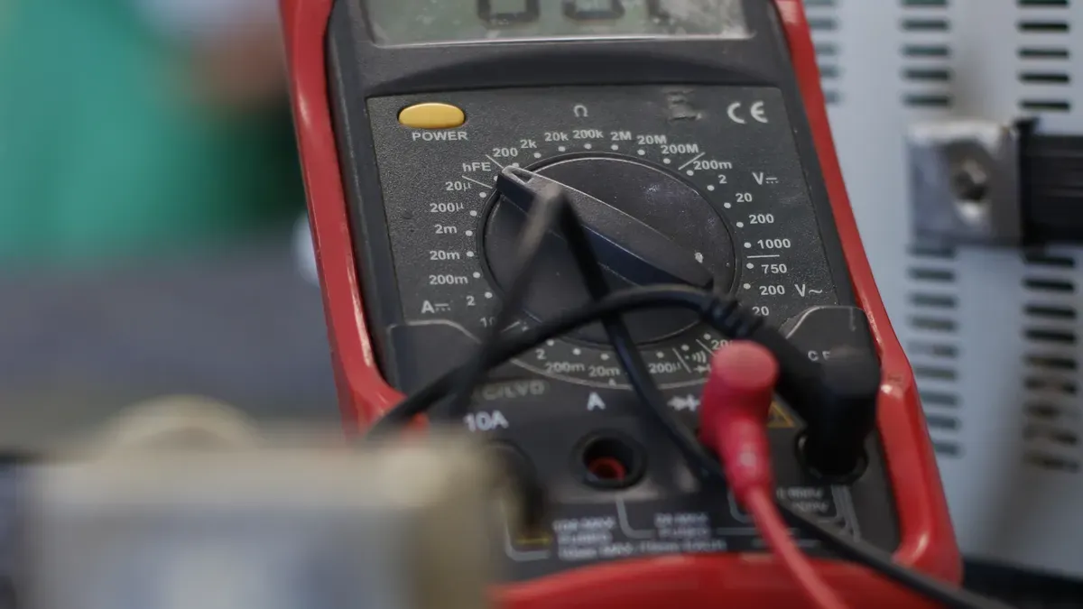
A four-wire Kelvin arrangement separates current injection from voltage sensing, reducing the contribution of test leads to the reading. Analog Devices’ low-resistance measurement guidance illustrates this principle.
Follow the connector specification’s test voltage, current, sense points and conditioning. Low-level contact tests and high-current temperature-rise tests answer different questions. Excessive test excitation can alter contact films or damage a small contact; do not default to 50-100 A because a busbar test uses that current.
Isolate and de-energize the component according to an approved procedure before resistance testing. Never connect an ordinary resistance meter across live battery output terminals. Testing a connector assembly separately can avoid interaction with cells and protection electronics.
3.2 Use Loaded Voltage Drop as a Complementary Test
On a controlled bench setup, measure differential voltage directly across the defined connection while recording actual load current. Estimate effective resistance as R = Vdrop / I under a suitable steady condition. Measuring from battery output to device input instead gives the loss of everything between those points.
Use an appropriate electronic load or representative device load, with protection and suitably rated measurement equipment. Household AC appliances are not a generic test load for a DC battery connector. Pulse measurements require synchronized voltage and current capture and suitable bandwidth.
3.3 Inspect and Measure Temperature Together
Check latch engagement, terminal retention, discoloration, deformation and cable strain. Under an approved load test, use appropriately placed temperature sensors or thermal imaging to locate hotspots. Reflective metal and emissivity can distort infrared readings; verify important results with a suitable contact measurement.
Live testing requires trained personnel and controlled access. Do not touch or disconnect a suspect live connection merely to see whether it feels hot. Damaged housings and terminals require assessment and replacement according to the manufacturer’s instructions.
Part4: Set Acceptance Limits for the Application
4.1 Combine Specification Limits with the System Budget
Use the exact connector’s initial and conditioned resistance limits, current derating and allowable operating temperature. Molex’s current-rating guidance for this terminal family, for example, ties its guideline ratings to specified wire and temperature-rise conditions. Such conditions are product-specific.
A first electrical budget is Rmax = allowed voltage loss / maximum relevant current. With a 0.15 V allocation at 15 A, the defined path has a 10 mΩ electrical budget. Thermal limits, tolerances and life-cycle margin may require a lower design target.
Do not apply a universal 20% increase rule to every connector. At very low resistance, measurement uncertainty can make a percentage change misleading. Evaluate absolute limits, repeatability, baseline trends and temperature together.
4.2 Validate After Relevant Stress
Validation condition | What to record |
|---|---|
Initial assembly | Defined resistance, load drop and hotspot temperature |
Mating cycles | Wear, retention and resistance change |
Vibration or cable movement | Intermittent discontinuities and terminal stability |
Humidity or contamination exposure | Corrosion, insulation condition and electrical change |
Maximum ambient and load duty | Temperature margin and voltage stability |
Production variation | Crimp/tooling consistency and worst-case assembly behavior |
Repeat measurements at the same sense points and controlled conditions. Define the samples, stress sequence and acceptance criteria before testing. A high-quality single sample does not establish production consistency.
Part5: Prevent Problems in Assembly and Service
5.1 Control Terminations and Mechanical Loads
Match terminal, wire size and insulation to the approved system. Use specified tooling and inspect crimps using appropriate dimensional and mechanical checks. Pull strength alone does not prove low electrical resistance. Provide strain relief and prevent terminal back-out.
For bolted joints, follow the specified torque, hardware and surface preparation. More torque is not always better: over-tightening can damage the joint. Push-fit spring connectors do not have a user torque requirement. Lubricants, cleaners or abrasives should be used only when approved for the contact system.
5.2 Plan Maintenance from the Actual Duty
Set inspection frequency according to the device instructions, environment, mating cycles and failure consequences. Do not copy flooded lead-acid or stationary nickel-cadmium maintenance schedules into a sealed portable lithium battery application.
Monitor resistance and temperature trends where service access permits. Replace damaged components, investigate the cause and verify the repair. For a new pack, provide connector type, load profile, enclosure conditions and expected mating life through custom battery consultation.
FAQ
How much contact resistance is too high?
Use the connector specification and the device’s voltage and thermal budgets. Define whether the limit covers one contact or the entire assembly. There is no single acceptable value for all battery connectors.
Can I use a standard multimeter?
A two-wire resistance reading is usually inadequate for precise milliohm measurements. A suitable meter can measure loaded voltage drop, while a four-wire instrument is preferred for controlled low-resistance testing.
Must I test at 100 A?
No. Use the excitation required by the connector’s test method and component rating. Small contacts can be damaged or their surface condition altered by excessive current.
Will the BMS detect connector overheating?
Not necessarily. A resistive contact can become hot without exceeding pack current limits, particularly when no sensor monitors that location.
Does contact resistance reduce runtime?
It wastes energy and lowers device input voltage under load. This can cause earlier cutoff, especially with high peak currents and limited voltage margin.
Should I retighten every battery connector?
No. Follow the interface instructions. Bolted joints have defined torque requirements; spring-contact connectors require correct mating and retention rather than retightening.


